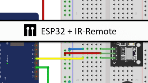
In this tutorial, you will learn how to use an IR remote with an ESP32. IR (Infrared) remotes are commonly used to control various electronic devices such as TVs, DVD players, and air conditioners. By integrating an IR remote with an ESP32, we can create a smart home automation system, control colorful lighting or build a remote-controlled robot.
The ESP32 is a powerful microcontroller that offers built-in Wi-Fi and Bluetooth capabilities, making it an ideal choice for IoT projects. With the help of an IR receiver module, we can receive and decode signals from an IR remote, allowing us to control different components and devices.
In this blog post, we will cover the necessary parts required for this project, understand how an IR remote works, and learn how to connect the IR receiver to the ESP32. We will also explore how to read IR signals, control an LED, dim an LED and sound a buzzer.
So, let’s go!
Required Parts
Below you will find the components required for this project. If you already have an IR remote, then you will not need the IR Remote Receiver Kit, just the IR Receiver Module. However, not all IR remotes will be suitable. On the other hand, if you buy or have the Kit you will not need the IR Receiver Module, since it is part of the Kit.
Also, for this project, I am using an older ESP32 board, which has been deprecated but you can still get it for a low price. That’s the one listed below. There is a successor model with improved specs, which you can find here.
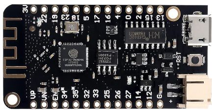
ESP32 lite
USB Data Cable

Dupont Wire Set

Breadboard

Resistor & LED kit
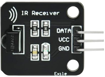
IR Receiver Module
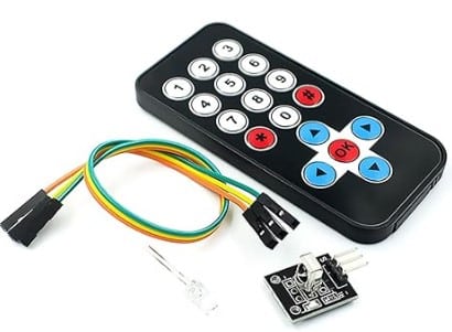
IR Remote Receiver Kit

Active Buzzer
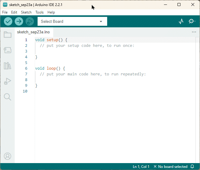
Arduino IDE
Makerguides.com is a participant in the Amazon Services LLC Associates Program, an affiliate advertising program designed to provide a means for sites to earn advertising fees by advertising and linking to products on Amazon.com. As an Amazon Associate we earn from qualifying purchases.
How does an IR Remote work
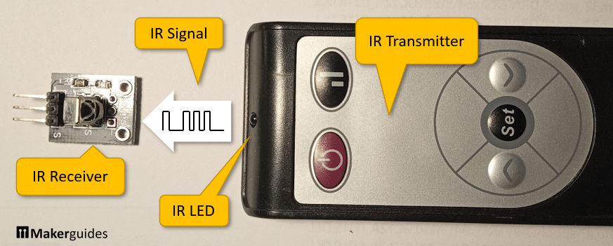
An IR (Infrared) remote control is a device that uses infrared light to transmit signals to control electronic devices. It uses an IR Transmitter and an IR LED to send IR signals to an IR Receiver:
Infrared Light
Infrared light (IR) is part of the electromagnetic spectrum, just like visible light, radio waves, and microwaves. However, it has a longer wavelength than visible light, making it invisible to the human eye.
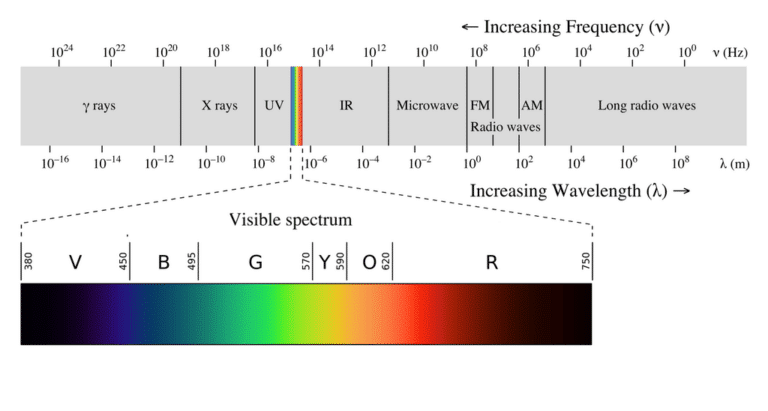
Infrared light is often used for communication purposes due to its low interference with other electronic devices.
IR vs. RF Radio vs. Bluetooth
Note that IR communication is different from RF Radio, and Bluetooth communication. While all three can be used for wireless communication, they have distinct characteristics.
IR communication is limited to line-of-sight transmission, meaning the receiver must be within the direct line of sight of the transmitter. It is commonly used for short-range communication, such as controlling devices in the same room.
RF Radio communication, on the other hand, uses radio waves to transmit signals. It has a longer range compared to IR and does not require line-of-sight transmission. RF Radio is used for wireless communication between devices, such as remote controls for garage doors or wireless keyboards.
Bluetooth is a wireless technology that operates in the 2.4 GHz frequency range. It offers a longer range than IR and supports bidirectional communication. Bluetooth is typically used for connecting devices like smartphones, headphones, and speakers.
IR Transmitter
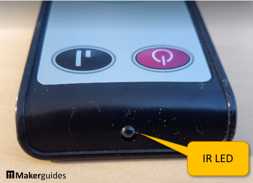
The IR transmitter is hidden in the remote control itself. It creates signals in a specific pattern to communicate with the IR receiver. The signals are converted to IR light with an IR LED. If you look closely you usually can see a clear LED at the front of the remote. That is the IR LED that emits the IR signal.
The most common protocol used for IR communication is the NEC (Nihon Electronics Corporation) protocol.
NEC Protocol for IR Communication
The NEC protocol defines a standard way of encoding and decoding data transmitted via infrared signals. This protocol is commonly used in consumer electronics, and chances are that most the IR remotes in your house are using it (the exception are air-conditioning units).
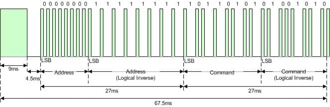
The NEC protocol uses a carrier frequency of 38 kHz, which means the infrared signal is modulated at this frequency. The modulated signal consists of bursts of infrared light, with each burst representing a binary digit (0 or 1).
To transmit data, the IR remote sends a series of bursts, each burst consisting of a data block with an Address, its inverse (complement), a Command, followed by its inverse. Essentially, every button on your remote is mapped to 32-bit data block, encoded as follows.
| NEC IR Protocol Frame Format | |||
| Address | Inverse of Address | Command | Inverse of Command |
| 0-7 bits | 8-15 bits | 16-23 bits | 24-31 bits |
The bits of the data block are converted to pulses, where a 0 bit is sent as 562.5µs high time + 562.5µs low time, and a 1 bit is sent as 562.5µs high time + 1.6875ms low time. On an oscilloscope, you would see a signal like this:
On the receiver side, an IR receiver module detects the bursts of infrared light and demodulates them to extract the binary data.
IR Receiver
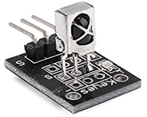
The IR receiver is the component that receives the infrared signals from the remote control. It consists of a photodiode that detects the incoming infrared light and converts it into electrical signals. Below you can see a typical IR receiver module.
In order to receive and decode the NEC protocol, the IR receiver needs to be connected to a microcontroller capable of reading and interpreting the incoming signals. This allows the microcontroller to understand the button presses and perform the desired actions.
In the next section, I will show you how to connect an IR receiver to an ESP32 board to receive and decode IR signals. Stay tuned!
Connecting the IR Receiver
Connecting the IR receiver module to the ESP32 is easy. The Fritzing circuit below shows you how it is done. Note that I am using a Lolin32 lite here. However, almost any other ESP32 development board will work as well.
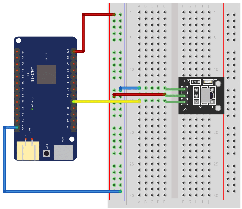
First we connect the ground pin (GND) of the ESP32 to the negative power rail of the breadboard, using a blue wire. Next we connect the positive rail of the breadboard (marked by a red line), with a red wire to the pin named 3.3V on the ESP32 board.
Now, since we have power on the breadboard we can connect the IR receiver module. Connect the pin marked with the (–) sign on the IR receiver module with a blue wire to the negative power rail of the breadboard. Then connect the pin marked with an (S) for Signal to Pin 4 on the ESP32 (yellow wire). Finally connect the remaining pin of the IR receiver with a red wire to the positive power rail. Done!
Decoding IR signals
To use our IR remote we need to know which button sends which code. The following code will help you to do this. For more details see our tutorial How to use an IR receiver and remote with Arduino.
#include "IRremote.hpp"

const int irReceiverPin = 4;

void setup() {
  Serial.begin(9600);
  IrReceiver.begin(irReceiverPin , ENABLE_LED_FEEDBACK);
}

void loop() {
  if (IrReceiver.decode()) {
    IrReceiver.printIRResultShort(&Serial);
    IrReceiver.resume();
  }
}
It works as follows: First we include the IRremote library. Then we define the constant irReceiverPin to let the library know to which pin the IR receiver is connected to.
The setup function
In the setup() function we initiate the serial communication at a baud rate of 9600, which allows the Arduino to communicate with the computer. Then we call the begin() function of the IrReceiver object, passing the irReceiverPin and ENABLE_LED_FEEDBACK as arguments. This initializes the IR receiver and enables LED feedback on the IR receiver module. That means, you will see an LED flicker, whenever you press a button on your remote and the module can see it.
The loop function
In the loop() function we check if there is a signal received by the IR receiver. If a signal is detected, the IrReceiver.decode() function returns true. In this case, we call IrReceiver.printIRResultShort(), which prints a short summary of the received infrared signal to the Serial monitor. Then, the IrReceiver.resume() function is called to prepare the IR receiver for the next signal.
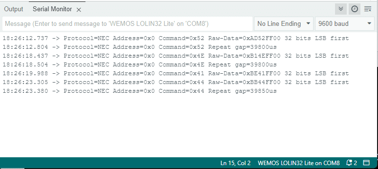
For example, If I press some buttons on my remote, I get the following output on the Serial monitor. You can see that the NEC protocol was discovered and which Address and Command values were sent.
Decoding my IR remote
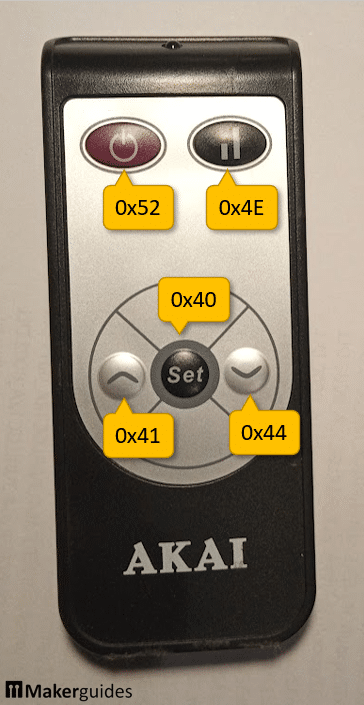
When I run the above code and write down the codes for the individual commands, I get the following mapping of buttons to commands for my IR remote:
| Button | Address | Command code |
|---|---|---|
| On/Off | 0x00 | 0x52 |
| Mode | 0x00 | 0x4E |
| Set | 0x00 | 0x40 |
| Up | 0x00 | 0x41 |
| Down | 0x00 | 0x44 |
Note that the Address (0x00) is always the same for all the buttons. That is usually the case but different IR remotes will have different addresses. For your IR remote this mapping of buttons and command codes will be different and you have to used the code above to find that out.
Once you have the codes for your IR remote you can uses it to control all kinds of devices. In the following sections I will give you some examples.
Switching an LED
In this section I will show you how to switch an LED on and off, using the On/Off button of the remote.
Circuit for switching an LED
First, we need to add an LED to our circuit. That is simple. I just place an LED on the breadboard and connect its Anode (the longer pin) via a 68Ω resistor to Pin 2 of the ESP32. Next, we connect the Cathode of the LED (the shorter pin) to ground on the breadboard.
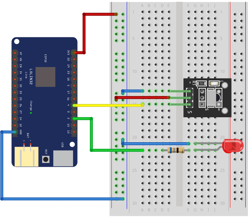
Note that the ESP32 board runs on 3.3V. That is why you need to use a fairly small value for the resistor compared to an Arduino circuit, which runs on 5V. With a larger resistor value the LED will still glow but weakly.
Code for switching an LED
Now we can use the following code to switch the LED on the board on or off.
#include "IRremote.hpp"

const int irReceiverPin = 4;
const int ledPin = 2;

void toggle(uint8_t pin) {
  auto state = digitalRead(pin);
  digitalWrite(pin, !state);
}

void setup() {
  pinMode(ledPin, OUTPUT);
  IrReceiver.begin(irReceiverPin, ENABLE_LED_FEEDBACK);
}

void loop() {
  if (IrReceiver.decode()) {
    uint16_t command = IrReceiver.decodedIRData.command;
    if (command == 0x52) {  // On/Off
      toggle(ledPin);
    }
    delay(100);
    IrReceiver.resume();
  }
}
The code is largely identical to the one before. We just add a new constant (ledPin) for the pin where the LED is connected to
const int ledPin = 2;
and a function that toggles the output state for that pin:
void toggle(uint8_t pin) {
  auto state = digitalRead(pin);
  digitalWrite(pin, !state);
}
Whenever we call this function, the state of the output switches from on to off and vice versa. This causes the LED to light up or go dark. However, you must not forget to define the pin as an output pin in the setup() function!
void setup() {
  pinMode(ledPin, OUTPUT);
  IrReceiver.begin(irReceiverPin, ENABLE_LED_FEEDBACK);
}
In the main loop we add an if statement that checks if the command code received is 0x52. That is the command code for the On/Off button we identified before.
void loop() {
  if (IrReceiver.decode()) {
    uint16_t command = IrReceiver.decodedIRData.command;
    if (command == 0x52) {  // On/Off
      toggle(ledPin);
    }
    delay(100);
    IrReceiver.resume();
  }
}
If that is the case we toggle the LED. Note that we don’t have to check the address sent by the IrReceiver, since it is always the same. However, if you want to react to signals from different remotes using the same IR receiver you may have to do this.
Finally, we wait for 100ms to avoid toggling the LED repeatedly, if the On/Off button is pressed a bit longer.
And that’s it. Now you can control an LED or a Relay or any other switching device via your IR remote.
Dimming an LED
Let’s try something a bit more advanced. Instead of simply switching the LED on or off, we are going to control its brightness. We use the same LED and circuit as before but change the code as follows:
#include "IRremote.hpp"

const int irReceiverPin = 4;
const int ledPin = 2;
const int inc = 10;

int brightness = 100;

void init() {
  pinMode(ledPin, OUTPUT);
  analogWrite(ledPin, brightness);
}

void execute(uint16_t command) {
  if (command == 0x41) {  // UP
    brightness = min(brightness + inc, 255);
  }
  if (command == 0x44) {  // DOWN
    brightness = max(brightness - inc, 0);
  }
  analogWrite(ledPin, brightness);
  delay(100);
}

void setup() {
  IrReceiver.begin(irReceiverPin, ENABLE_LED_FEEDBACK);
  init();
}

void loop() {
  if (IrReceiver.decode()) {
    execute(IrReceiver.decodedIRData.command);
    IrReceiver.resume();
  }
}
To understand this code let’s have a look at the setup and the loop functions first. They tend to be largely identical for most applications, so I made it as generic as possible. In the setup function, I call an init() function that initializes pins and other things. And in the loop function I call an execute() function, that executes a command received from the IR remote.
void setup() {
  IrReceiver.begin(irReceiverPin, ENABLE_LED_FEEDBACK);
  init();
}

void loop() {
  if (IrReceiver.decode()) {
    execute(IrReceiver.decodedIRData.command);
    IrReceiver.resume();
  }
}
With this framework we can keep the setup() and the loop() function the same for different applications and only have to implement or modify the init() and the execute() functions.
The init function
For instance, to control the brightness of the LED, we implement the init() function as follows:
void init() {
  pinMode(ledPin, OUTPUT);
  analogWrite(ledPin, brightness);
}
This sets the LED pin as output and we also set the initial brightness of the led via analogWrite(), where brightness is a variable we defined.
The execute function
The execute() function takes a command received from the IR remote and if the command is 0x41 (up button) it increases the brightness. If the command is 0x44 (down button) it decreases the brightness.
void execute(uint16_t command) {
  if (command == 0x41) {  // UP
    brightness = min(brightness + inc, 255);
  }
  if (command == 0x44) {  // DOWN
    brightness = max(brightness - inc, 0);
  }
  analogWrite(ledPin, brightness);
  delay(100);
}
To change the brightness we add or subtract a predefined increment (inc) value. Larger increments will chance the brightness more quickly. Smaller increments will give us a smoother but slower change.
We use analogWrite() to write the brightness value to the ledPin. However, the range of values you can write to an analog output is limited from 0 to 255. We need to be careful and avoid values beyond this ranges. That is why we use the the min() and max() functions here. They ensure that our increments do not cause the brightness value to exceed the valid range.
Finally, analogWrite() requires that the output pin supports PWM (Pulse Width Modulation). But on ESP32 development board most pins support PWM, so that is usually now a problem. If in doubt check the pinout and look for a wavy symbol.
In the next section we will use the same framework and working principle to control the frequency of a buzzer.
Sounding a Buzzer
Similar to the brightness of LEDs, the frequency of an active buzzer can be controlled via a PWM signal. That means, with a few tweaks we can essentially use the same code as above. But first let’s build the circuit.
Circuit for sounding a Buzzer
We remove the LED and replace it by a Buzzer. We don’t need a resistor and just have to make sure that we connect the negative pole of the Buzzer to the negative power rail of the breadboard and the positive pole to Pin 2 of the ESP32.
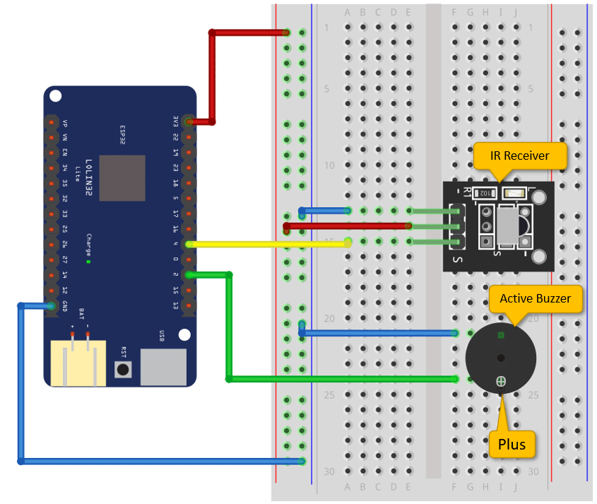
Note that buzzer tend to have a faint plus sign on the top that indicates the plus pole. Since it is hard to see, make sure that you connect the plus side to Pin 2 of the ESP32. Also make sure, that you have an active buzzer and not a passive one.
Code for sounding a Buzzer
As promised, the code to control the buzzer is very similar to the one for the LED.
#include "IRremote.hpp"

const int irReceiverPin = 4;
const int buzzerPin = 2;
const int inc = 10;

int freq = 1000;
bool do_sound = false;

void init() {
  pinMode(buzzerPin, OUTPUT);
  noTone(buzzerPin);
}

void execute(uint16_t command) {
  switch (command) {
    case 0x41:  // Up
      freq = min(freq + inc, 65535);
      break;
    case 0x44:  // Down
      freq = max(freq - inc, 0);
      break;
    case 0x52:  // Stop
      do_sound = !do_sound;
      delay(100);
      break;
  }
  do_sound ? tone(buzzerPin, freq) : noTone(buzzerPin);
  delay(10);
}

void setup() {
  IrReceiver.begin(irReceiverPin, ENABLE_LED_FEEDBACK);
  init();
}

void loop() {
  if (IrReceiver.decode()) {
    execute(IrReceiver.decodedIRData.command);
    IrReceiver.resume();
  }
}
In the init() function we set the pin the buzzer is connected to, to output mode. Then we make sure the buzzer is switched off at the start by calling noTone().
void init() {
  pinMode(buzzerPin, OUTPUT);
  noTone(buzzerPin);
}
Note that noTone() and tone() are built in Ardunio functions. You don’t need to include an additional library to use them.
In the execute() function we again listen for a command from the IR receiver and react to it.
void execute(uint16_t command) {
  switch (command) {
    case 0x41:  // Up
      freq = min(freq + inc, 65535);
      break;
    case 0x44:  // Down
      freq = max(freq - inc, 0);
      break;
    case 0x52:  // Stop
      do_sound = !do_sound;
      delay(100);
      break;
  }
  do_sound ? tone(buzzerPin, freq) : noTone(buzzerPin);
  delay(10);
}
If the Up button (0x41) is pressed we increase the frequency and if the Down button (0x44) is pressed we decrease it. Valid values for the frequency are in the range from 0 to 65535. So, as before, we use min() and max() to limit the range of values.
I also wanted to be able to switch the sound on or off. Therefore the code also watches for the Stop button (0x52) and toggles the boolean variable do_sound. After that we add a delay of 100ms so that the switching is not too fast.
The last thing we need to do, is to actually play the sound, which is achieved by this line of code:
do_sound ? tone(buzzerPin, freq) : noTone(buzzerPin);
If do_sound is True, we play the tone at the set frequency, otherwise we switch the buzzer off.
The setup() and the loop() function are the same as before. There you go! Now you have three examples on how use an IR remote control different devices. You also have a nice little code framework, where you just have to implement the init() and execute() functions to control other devices.
For instance, if you want to control motors have a look at our tutorials on How to Control a Servo with an IR Remote and Control a Stepper Motor with an IR Remote.
Finally, this circuit and code only allows you to receive IR signals. If you want to send signals read How to build a universal, programmable IR remote.
Conclusion
In this tutorial, we have learned how to use an IR remote with an ESP32. We started by understanding the required parts for this project, which include an ESP32 board and an IR receiver.
Next, we explored how an IR remote works and how it sends signals to the IR receiver. We then moved on to connecting the IR receiver to the ESP32 board, ensuring that the necessary pins are properly connected.
Once the hardware setup was complete, we dove into the code and learned how to read the IR signals using the IRremote library. We implemented various functionalities, such as switching an LED on and off, dimming an LED, and sounding a buzzer, based on the received IR signals.
By following this tutorial, you should now have a good understanding of how to integrate an IR remote with an ESP32 and control different components using the signals received. This opens up a wide range of possibilities for your projects, from creating a remote-controlled home automation system to building a custom remote for your own applications.
If you have any further questions or face any issues while working on this project, please refer to the Frequently Asked Questions section below. Additionally, you can find useful links to relevant resources and documentation to further enhance your knowledge and skills in this area.
Happy tinkering!
Frequently Asked Questions
Here are some commonly asked questions about using an IR remote with an ESP32:
Q: Can I use any IR remote?
A: Yes, the IRRemote library and the IRReceiver module we used here, understands most standard IR remotes. Another possible choice is the IRremoteESP8266 library. However, it is important to check the frequency compatibility of the remote with the IR receiver module you are using.
Q: How do I find the IR codes for my remote?
A: There are a few different methods you can use to find the IR codes for your remote. One way is to use an IR receiver module and an Arduino or ESP32 to capture and decode the signals as we have shown above. Or you buy a simple Component tester that can decode IR signals. The last option is to search online for the specific remote model and see if the codes are available.
Q: Can I control multiple devices with one IR remote?
A: Yes, you can control multiple devices with a single IR remote by using different IR codes for each device. By decoding the IR signals and mapping them to specific actions, you can control various devices such as LEDs, motors, or even home appliances.
Q: How far can the IR remote signal reach?
A: The range of an IR remote depends on various factors, including the power of the remote, the sensitivity of the IR receiver, and any obstacles in the line of sight. Generally, the range can vary from a few meters to around 10 meters.
Q: Can I use an IR remote with other microcontrollers or development boards?
A: Yes, IR remotes can be used with various microcontrollers and development boards. See our tutorial on How to use an IR receiver and remote with Arduino, for instance.
If you have any other questions or need further assistance, feel free to ask in the comments section below.
Links
Below you will find some links for further information
- IRremote library documentation
- ESP32 board documentation
- How to build a universal, programmable IR remote
- How to Control a Servo with an IR Remote
- Control a Stepper Motor with an IR Remote
- IR Remote control codes database
- IR Remote Control Basics
- IR Remote Control with Arduino
- The ESP32-based IR remote control for household appliances
- ESP32 – IR Remote Control
Stefan is a professional software developer and researcher. He has worked in robotics, bioinformatics, image/audio processing and education at Siemens, IBM and Google. He specializes in AI and machine learning and has a keen interest in DIY projects involving Arduino and 3D printing.