In this tutorial, we will learn how to control a servo motor using an IR remote and an Arduino. Servo motors are widely used in various projects, including robotics, automation, and remote-controlled vehicles. By integrating an IR sensor with an Arduino board, we can receive commands from an IR remote and use them to control the position or speed of the servo motor.
Controlling a servo motor with an IR remote opens up a world of possibilities. You can use it to build a remote-controlled robot arm, create a pan-tilt mechanism for a camera, or even build a remote-controlled car. The possibilities are endless!
Before we dive into the details, let’s take a look at the components you will need for this project.
Required Components
Makerguides.com is a participant in the Amazon Services LLC Associates Program, an affiliate advertising program designed to provide a means for sites to earn advertising fees by advertising and linking to products on Amazon.com. As an Amazon Associate we earn from qualifying purchases.
Below you will find the components required for this project. If you already have an IR remote, then you will not need the IR Remote Receiver Kit, just the IR Receiver Module. However, not all IR remotes will be suitable. On the other hand, if you buy or have the Kit you will not need the IR Receiver Module, since it is part of the Kit.

Arduino Uno

Dupont Wire Set

Breadboard

USB Cable for Arduino UNO
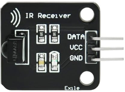
IR Receiver Module

IR Remote Receiver Kit
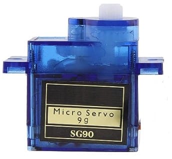
Servo
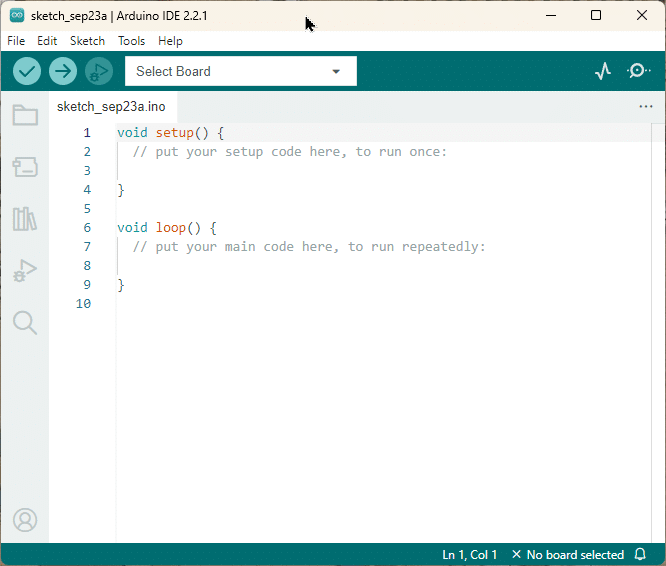
Arduino IDE
Connecting the Components
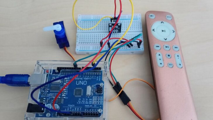
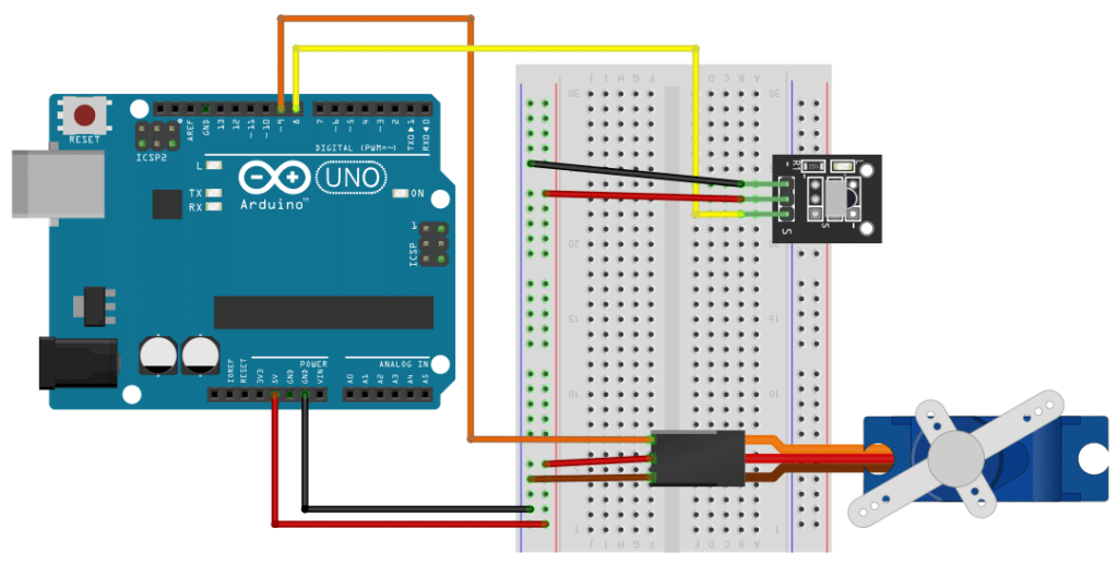
In this section we will connect the components to the Arduino. The picture below shows you the complete wiring. We start with the power supply to the breadboard.
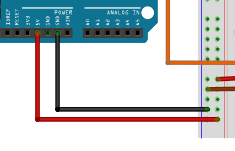
Connecting the Breadboard
First, connect the pin marked Ground (GND) on the Arduino with a black or blue wire to the Ground rail of the breadboard (marked with a blue line). Then connect, the pin marked 5V (Power) on the Arduino with a red wire to the Power rail of the breadboard (marked with a red line).
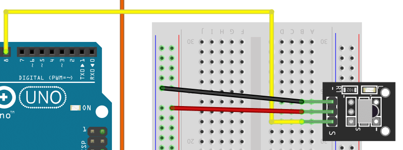
Connecting the IR Sensor
We start with the signal wire to connect the IR sensor. Find the pin marked S or Signal on the IR sensor module and connect it with a yellow wire to pin 8 on the Arduino.
Next we connect the power. Typically, plus is the middle pin on IR sensor module. Use a read wire to connect that pin to the positive power rail of the breadboard. Finally, connect the remaining, third pin on the IR sensor module to the negative power rail of the breadboard.
Connecting the Servo Motor
The last component to connect, is the servo motor. First, connect the brown wire of the servo motor to the negative power rail of the breadboard with a brown or black wire. Then connect the red wire of the servo to the positive power rail; preferably with a red wire.
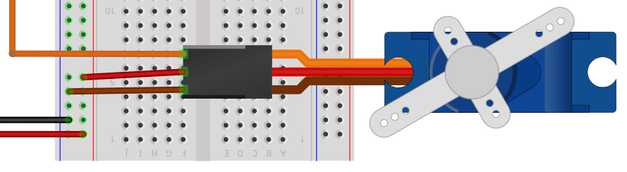
Finally we connect the orange signal wire of the servo to pin 9 on the Arduino board.

Once you are finished with the wiring of the components better double check that everything is correctly connected. Take special care of the power connections. We don’t want to have a shortcut.
Next, I’ll show you the code needed.
Writing the Arduino code
Below you find the complete code for an overview. It allows you to rotate the servo left or right in steps of 10 degrees by pressing the NEXT or PREV button on the remote. Let’s break this code into pieces and explain its function.
#include <IRremote.hpp>
#include <Servo.h>

#define IR_RECEIVE_PIN 8
#define SERVO_PIN 9

Servo servo;
const int range = 780;
const int mid = 1600;

int pos = 90;
int speed = 10;

void rotate(int angle) {
  angle = map(angle, 0, 180, mid - range, mid + range);
  servo.writeMicroseconds(angle);
}

void setup() {
  IrReceiver.begin(IR_RECEIVE_PIN, ENABLE_LED_FEEDBACK);
  servo.attach(SERVO_PIN);
  rotate(pos);
}

void loop() {
  if (IrReceiver.decode()) {
    uint16_t command = IrReceiver.decodedIRData.command;
    if (command == 8) {  // NEXT
      pos = min(pos + speed, 180);
    } else if (command == 2) {  // PREV
      pos = max(pos - speed, 10);
    }
    rotate(pos);
    IrReceiver.resume();
  }
}
Definitions
First we include two libraries. The IRremote library, which is needed to understand the commands the IR remote is sending. And the Servo library, which helps us to control the servo.
#include <IRremote.hpp>
#include <Servo.h>
We then define constants, IR_RECEIVE_PIN and SERVO_PIN that specify which pins on the Arduino are used to read the IR signal and to control the servo.
#define IR_RECEIVE_PIN 8
#define SERVO_PIN 9
After that we define the servo object and two constants (range and mid), which adjust the range of motion for the servo, and mid define the middle position of the servo. In addition, we declare two variables (pos, speed) that describe the current position of the servo and the speed (or angle steps), it rotates with.
Servo servo;
const int range = 780;
const int mid = 1600;

int pos = 90;
int speed = 10;
Rotating the servo
To rotate the servo to a specific angle, we define a special rotate() function. It essentially maps the given angle, which must be between 0 and 180 degrees, to the corresponding pulse length required to control the servo.
void rotate(int angle) {
  angle = map(angle, 0, 180, mid - range, mid + range);
  servo.writeMicroseconds(angle);
}
For more details see our tutorial on the differences between continuous and positional servos. Take special notice of the section that explains how to fine-tune you servo.
Setup
In the setup() function, we simply let the IR receiver library and the Servo library know, which pins are used for the IR receiver and the servo control. In addition, we rotate the servo to the 90 degree position. Note that we assume the common positional servo here.
void setup() {
  IrReceiver.begin(IR_RECEIVE_PIN, ENABLE_LED_FEEDBACK);
  servo.attach(SERVO_PIN);
  rotate(pos);
}
Main loop
Finally, we implement the loop() functions that runs continuously.
void loop() {
  if (IrReceiver.decode()) {
    uint16_t command = IrReceiver.decodedIRData.command;
    if (command == 8) {         // NEXT
      pos = min(pos + speed, 180);
    } else if (command == 2) {  // PREV
      pos = max(pos - speed, 10);
    }
    rotate(pos);
    IrReceiver.resume();
  }
}
We start by waiting for a signal from the IR receiver by calling IrReceiver.decode(). If we received a command, we decode it via IrReceiver.decodedIRData.command.
Depending on the value of the command we then either increase the position, but not more then 180 degrees, or decrease the position, but not lower than 0 degrees. That is what the min() and max() functions are for.
Which command value corresponds to which key on IR remote will depend on the remote you are using! See our tutorial on How to use an IR receiver and remote with Arduino to learn how to identify the command codes of your remote. In my case, 8 maps to the next track button and 2 maps to the previous track button on my remote.
Finally we rotate the servo to the position using rotate(pos) and let the IR receiver know to look for an new command via IrReceiver.resume().
Tipps
Note that you can increase the stepping angle or speed by which the servo moves between positions by increasing or decreasing the value of the speed variable. You could even do this using the remote just by adding two more commands to react to, for instance:
void loop() {
  if (IrReceiver.decode()) {
    uint16_t command = IrReceiver.decodedIRData.command;
    if (command == 31) {  // VOL+
      speed = min(speed + 1, 90);
    } else if (command == 23) {  // VOL-
      speed = max(speed - 1, 1);
    } else if (command == 8) { // NEXT
      pos = min(pos + speed, 180);
    } else if (command == 2) {  // PREV
      pos = max(pos - speed, 10);
    }
    rotate(pos);
    IrReceiver.resume();
  }
}
Here I use the volume buttons on my remote to control the speed. As before, the command codes for your remote may be different from yours and you will have to adjust the code accordingly.
Applications
Robotic Arm
Use the servo motor to control the movement of a robotic arm. The arm can be programmed to perform various tasks like picking up objects, moving them around, or even playing games.
Window Blinds Control
Automate the opening and closing of window blinds using the servo motor and IR remote. This allows you to control the amount of sunlight entering a room with just a press of a button.
Pet Feeder
Create an automated pet feeder that dispenses food at specific times using the servo motor. Use the IR remote to manually trigger the feeding process if needed.
Plant Watering System
Build a plant watering system that uses the servo motor to control the flow of water. Use the IR remote to activate the system and water your plants remotely.
Smart Door Lock
Build a smart door lock system that uses the servo motor to lock and unlock the door. Use the IR remote to remotely control the lock or set up a keypad for secure access.
Mood Lighting
Create a mood lighting system that uses the servo motor to adjust the brightness or color of the lights. Use the IR remote to change the lighting settings and create different atmospheres.
Automated Curtains
Control the opening and closing of curtains using the servo motor and IR remote. This allows you to easily adjust the amount of light entering a room or create privacy.
Robotic Fish Tank Cleaner
Build a robotic fish tank cleaner that uses the servo motor to move around and clean the tank. Use the IR remote to control its movements and cleaning patterns.
Interactive Art Installation
Create an interactive art installation that uses the servo motor to control moving parts or sculptures. Use the IR remote to trigger different movements and engage viewers.
Conclusions
In this tutorial, we have learned how to control a servo motor using an IR remote. By following the steps outlined in this guide, you can easily implement this functionality in your own projects.
We started by gathering the required components, including an Arduino Uno, a Dupont wire set, a breadboard, an IR receiver module, an IR remote receiver kit, and the Arduino IDE. These components are essential for building the circuit.
Next, we connected the components together. We connected the breadboard to the Arduino Uno, ensuring that all the connections were correct. Then, we connected the IR sensor to the breadboard and the servo motor to the Arduino Uno. These connections allow the Arduino to receive signals from the IR remote and control the servo motor accordingly.
After the hardware setup was complete, we moved on to writing the Arduino code. We defined the necessary variables and libraries, and then implemented the code to rotate the servo motor based on the signals received from the IR remote. We also set up the initial servo position in the setup function and continuously checked for IR remote signals in the main loop.
Finally, we provided some tips to enhance your servo motor control with an IR remote. These tips include using different buttons on the remote to trigger different servo movements, adjusting the servo speed, and incorporating other sensors or modules into your project.
In conclusion, controlling a servo motor with an IR remote opens up a wide range of possibilities for your Arduino projects. Whether you want to build a robotic arm, a camera gimbal, or any other project that requires precise motor control, this tutorial has provided you with the necessary knowledge to get started.
If you have any further questions or need clarification on any of the steps outlined in this tutorial, please refer to the Frequently Asked Questions section below. Happy making!
Frequently Asked Questions
Here are some common questions related to controlling a servo motor with an IR remote:
Q: Can I use any IR remote with this project?
A: Yes, you can use any IR remote as long as it is compatible with the Arduino. Most IR remotes use the NEC protocol, which is supported by the Arduino’s IR library. However, if you have a different type of IR remote, you may need to modify the code accordingly. You most likely you will have to adjust the code to the command codes of your remote. For details see here.
Q: How do I find the codes for my IR remote buttons?
A: To find the codes for your IR remote buttons, you can use the IRrecvDumpV2 example sketch provided by the Arduino’s IR library. Alternatively, follow our tutorial.
Upload the sketch to your Arduino, open the Serial Monitor, and press the buttons on your remote. The codes will be displayed in the Serial Monitor. You can then use these codes in your Arduino code to map the buttons to specific servo motor movements.
Q: Can I control multiple servo motors with one IR remote?
A: Yes, you can control multiple servo motors with one IR remote. You will need to connect each servo motor to a separate pin on the Arduino and modify the code to control each servo motor independently. You can assign different buttons on the IR remote to control different servo motors.
Q: How do I adjust the range of motion for the servo motor?
A: The range of motion for the servo motor can be adjusted by modifying the values in the servo.attach() and servo.write() functions in the Arduino code. The servo.attach() function sets the range of motion for the servo motor, while the servo.write() function specifies the angle at which the servo motor should move. For an alternative methods, have a look at our tutorial on continuous and positional servos.
Q: Can I use a different microcontroller instead of Arduino?
A: Yes, you can use a different microcontroller instead of Arduino as long as it supports the necessary libraries and has enough digital pins to connect the servo motor and IR receiver. The code provided in this tutorial is specific to Arduino, but you can adapt it to work with other microcontrollers.
Q: Can I use a different type of motor instead of a servo motor?
A: No, this specific project is designed to control servo motors. Servo motors have built-in position control, which makes them ideal for this application. If you want to control a different type of motor, you will need a different circuit and different code.
Q: Can I control the speed of the servo motor?
A: It depends. For continuous or 360 degree servos you can control the speed and direction (but not the position). For positional servos, which were used in this tutorial, you cannot directly control the speed but can change the angle steps, which sort-of changes the speed but it results in a jerky motion.
Q: Are there any safety precautions I should take when working with servo motors?
A: Yes, when working with servo motors, make sure to provide enough power to the servo motors and avoid overloading them. Also, be cautious of any moving parts and avoid touching them while the motor is in operation.
I hope these frequently asked questions have helped clarify any doubts you may have had. If you have any more questions, feel free to ask in the comments section below.
Links
Finally, a selection of links to related material you may find useful.
- How to Control a 360 Degree Servo Motor with Arduino
- How to Drive Servo Motors Using ESP32
- How to Control Servo Motors with Arduino (3 Examples)
- Control 360-degree Servo Motor Using ESP32
- Positional versus Continuous Servos
- Controlling Servo Motor with IR Remote
- Servo Motor Control with Remote
- Controlling a Servo with IR | Using an Infrared Library
- Controlling Servo Motor With Ir Remote Using Arduino
- Controlling Servo Motor Using IR Remote Control
Stefan is a professional software developer and researcher. He has worked in robotics, bioinformatics, image/audio processing and education at Siemens, IBM and Google. He specializes in AI and machine learning and has a keen interest in DIY projects involving Arduino and 3D printing.