In this tutorial you will learn how to drive power LEDs with the LD1500SB LED driver and an ESP32. Normal LEDs can be directly controlled from a GPIO pin. However, if you want to drive super bright LEDs, like the Cree-LEDs in your Flashlight, you need an LED driver.
Let’s get started!
Required Parts
For this project, I am using an older ESP32 board (ESP32 lite), which has been deprecated but you can still get it. That’s the one listed below. There is a successor model with improved specs, which you can find here. But any other ESP32, ESP8266 or Arduino boards will work as well for this project.
The provided link for the power LED is for a white color LED but you can get all kinds of colors and different color temperatures (e.g. warm white vs cool white). The LD1500SB can even drive small COB LEDs.
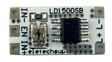
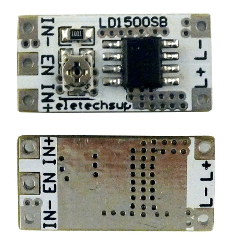
LD1500SB LED Driver
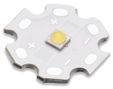
High Power LED (White)
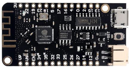
ESP32 lite
USB Data Cable

Dupont Wire Set

Breadboard
Makerguides.com is a participant in the Amazon Services LLC Associates Program, an affiliate advertising program designed to provide a means for sites to earn advertising fees by advertising and linking to products on Amazon.com. As an Amazon Associate we earn from qualifying purchases.
High-power LEDs
The high-power LED, we are going to use here, can draw a current of up 700mA and produces up to 170 Lumen of light. In contrast, to standard LED, high-power LEDs are much, much brighter than normal LEDs (100x and more) and can light up a room.
However, they also get very hot and may need extra cooling. The little aluminium cooling plate attached to the power LED is okay for up to 100mA. If you go higher for longer periods you should attach an additional cooling element.
The technical specification of the power LED above is as follows:
- current up to 700mA (continuously)
- peak pulse current 1000mA
at 1/10 duty cycle and 0.1ms pulse width - voltage: 3.2-3.6V
- power: 3W
- 170 Lumen at 700mA (typical)
Another disadvantage of a high-power LED is that we can’t control it directly from a GPIO pin of an ESP32 or Arduino, since the GPIO output current is limited to about 20mA. We need an LED driver and in the next section we have a closer look at the LD1500SB LED driver.
The LD1500SB LED driver
LED drivers provide the necessary power regulation for high-power LEDs. Most importantly they maintain a constant current flow through the LED to avoid overheating. This can easily happen, since the resistance of LEDs changes when they get hot. Without current regulation, LEDs can be damaged.
LED drivers convert an input voltage to a regulated current and output voltage that is suitable to drive one or multiple LEDs. For instance, the LD1500SB LED driver we are using in this project takes a DC input voltage of 2.9-6.1V and can drive up to 16 LEDs. Below are the specification details of the LD1500SB driver:
- Input voltage: DC 2.9-6.1V
- For 3V 3.3V 3.7V 5V 6V LEDs
- Output Current: 28-1500MA
- Maximum output power: 8W
- Output Current Accuracy: ± 5%
- Low Dropout Voltage: 0.37V @ 1.5A
- Can drive 1-16pcs 2.9-6.1V LEDs
- Maximum current 1.5A
- Current regulation:
through adjustable resistance or PWM control
One specific advantage of the LD1500SB is the low minimum input voltage of 2.9V. This means we can run this driver together with an ESP32 on a LiPo battery (3.7V). For instance, the LD24AJTA and the LD24AJTA_MINI LED drivers, have a minimum input voltage of 6V.
Another advantage is that the board is very small and noiseless. The LD24AJTA and LD24AJTA _MINI drivers are switching regulators that produce a high frequency noise, which can be annoying.
One disadvantage of the LD1500SB is that the maximum input voltage of 6.1V is low compared to the 25V of the LD24AJTA and LD24AJTA _MINI. For more information on other LED drivers, power LEDs and the LD24AJTA and LD24AJTA _MINI, see our tutorials Control Power LEDs with LD24AJTA and Arduino and Dim High-Power LED with Arduino and LD24AJTA_MINI.
CN5711 Current Regulation IC
Internally the LD1500SB is using the CN5711 current regulation IC and inherits most of its features from it. Here is a link to the Datasheet of the CN5711. The LD1500SB driver board essentially adds just two resistors to the IC. Below you can see the schematics of the LD1500SB:
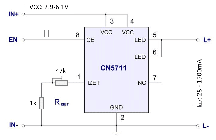
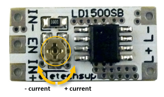
There is a fixed resistor RISET of 1KΩ and a variable resistor of 47KΩ that control the output current. You can manually adjust the maximum output current using the variable resistor. The picture below shows the location of this variable resistor on the LD1500SB board:
Note that in contrast to the LD24AJTA and LD24AJTA _MINI, the variable resistor overrides the PWM signal on the EN (Enable) input. Which means you have to manually adjust the resistor and the PWM signal to regulate the output current.
Pinout of the LD1500SB
The picture below shows the Pinout and the Typical Application Circuit of the LD1500SB LED driver. The input voltage of 2.9-6.1V needs to be connected to IN- and IN+, while the PWM signal must be connected to the EN pad.
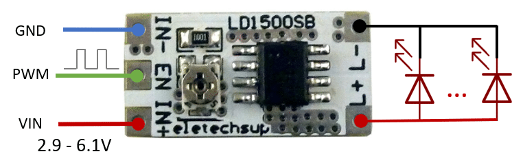
The LEDs are connected in parallel to the L+ and L- output on the other side of the board. According the specification you can connect up to 16 LEDs as long as they don’t exceed the maximum output current of 1500mA.
In the next section I show you, how to connect the LD1500SB to the ESP32 lite to control a power LED.
Connecting the LD1500SB and ESP32
Connecting the LD1500SB is easy. In the following circuit I am using a LiPo battery as power supply to the ESP32 lite and the power LED.
First, let’s connect the plus and minus outputs of the LiPo battery to the power supply inputs of the ESP32 lite and the LD1500SB board (red and black wires).
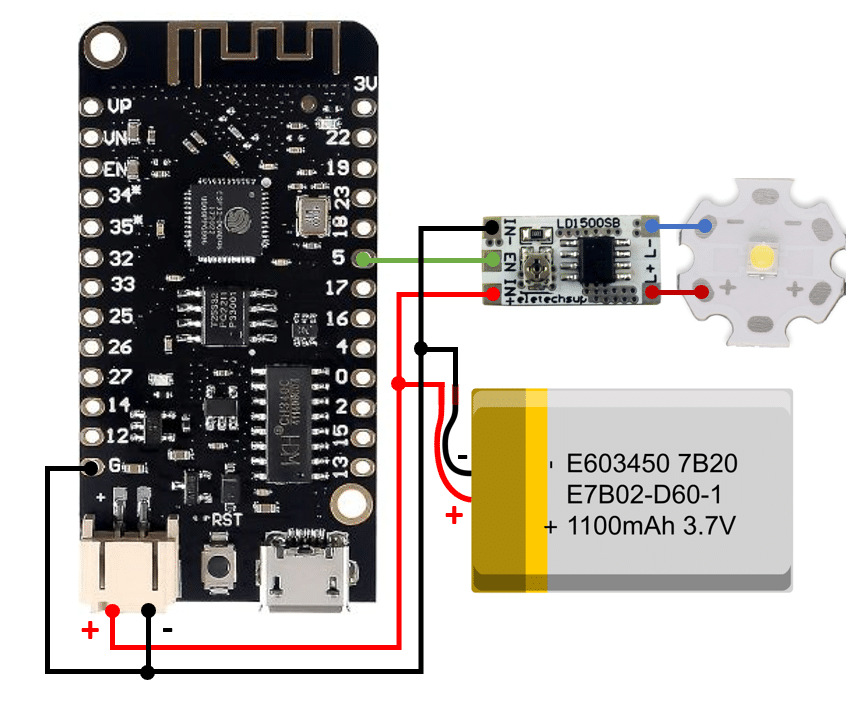
Note that I added a ground connection (G) from the ESP32 to the LiPo (black wire) to make sure LiPo battery, board and ESP32 share the same ground, even when the ESP32 is connected via USB.
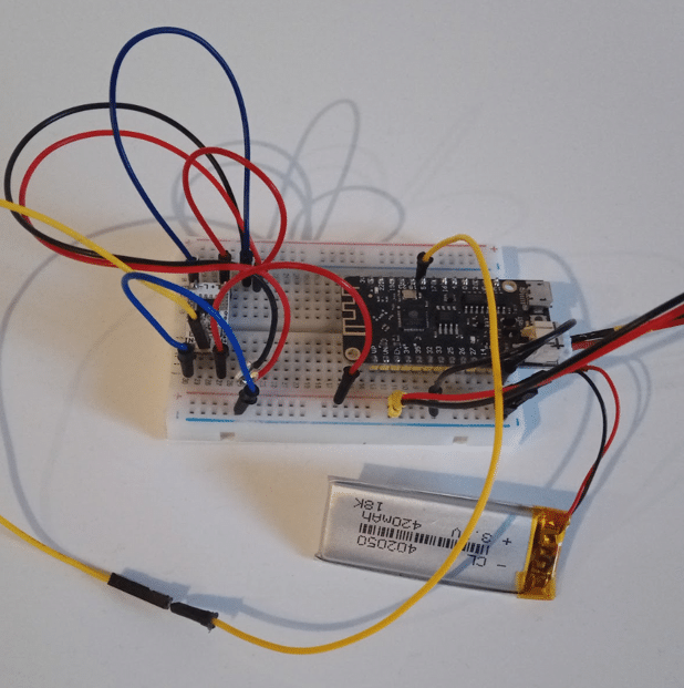
Next, we connect the power LED. The L- output of the LD1500SB needs to be connected to negative pole of the LED and the L+ output to the positive pole (blue and red wires). Below can see how the circuit looks like on a real breadboard:
And that’s it. You can now connect the ESP32 lite to your computer via USB and it will charge the LiPo (and still run its program). If you disconnect the USB the ESP32 lite will run on battery.
In the next section I’ll show you some example code to control the LED.
Code to control Power LEDs with LD1500SB and ESP32
Controlling the Power LED through the LD1500SB doesn’t require any special code. You could use the common Blink program to test the circuit. However, before you do that you better check that the output current is not too high!
Adjusting output current
Start by writing a small PWM value, e.g. 10 via analogWrite() to the pin the LED is connected to.
const byte ledPin = 5;

void setup() {
  pinMode(ledPin, OUTPUT);
}

void loop() {
  analogWrite(ledPin, 10);
  delay(1000);
  analogWrite(ledPin, 0);
  delay(1000);
}
Before uploading and running the code add a Multimeter to the circuit as shown below. We need it to measure and adjust the output current that flows through the LED:
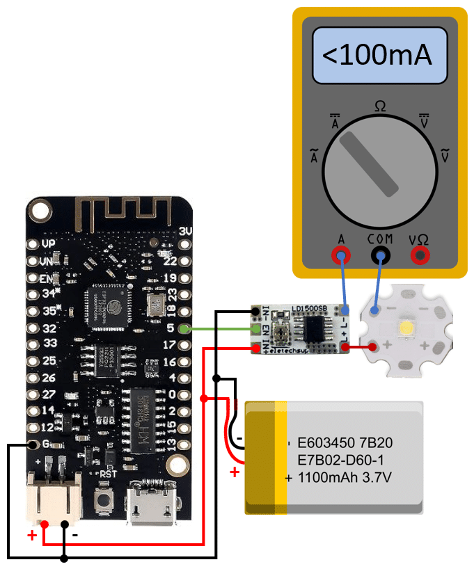
Make sure that the Multimeter is connected and set for DC current measurements. Now you can upload and run the code. Watch the Multimeter and keep the current below 100mA. If you go higher, you will need extra cooling for the LED or switch it on only for very short periods of time (e.g. flashing).
You have two ways to adjust the output current. Either you change the PWM values or you turn the variable resistor on the LD1500SB board. The best way is to slowly raise the PWM value up to its maximum of 255 and at the same time adjust the variable resistor to keep the output current below 100mA.
Once you have adjusted the output current you can write the same code you usually would write to control a normal LED. In the next section we write code to dim the Power LED.
Dimming the LED
Assuming you have adjusted the output current, you can dim the LED with this code. It slowly raises the brightness from 0 to the maximum of 255 and then switches of the LED for one second. That cycle repeats indefinitely.
const byte ledPin = 5;

void setup() {
  pinMode(ledPin, OUTPUT);
}

void loop() {
  for (int b = 0; b < 255; b++) {
    analogWrite(ledPin, b);
    delay(100);
  }
  analogWrite(ledPin, 0);
  delay(1000);
}
And that’s it. Now you know how to use the LD1500SB LED Driver to control Power LEDs!
Conclusion
In this tutorial you learned how to control a Power LED with an ESP32 using the LD1500SB LED driver. The same circuit and code would work with an ESP8266 or Arduino. But if you want to power it with a LiPo battery, aim for a microcontroller that runs on 3.3V.
The wiring and function of the LD1500SB LED driver is very similar to the LD24AJTA and the LD24AJTA_MINI LED drivers we have used in similar projects. The biggest difference is the lower input voltage of 2.9V. This makes is especially suitable for small battery powered projects that rely on a single LiPo battery or rely on the 3.3V or 5V power supply from the microcontroller.
However, the comparatively low maximum input voltage of 6.1V limits is applications. The LD24AJTA with a maximum of 25V allows a wider range of power supply options.
Have fun playing with Power LEDs and if you have any questions don’t hesitate to ask!
Frequently Asked Questions
Q: How do I connect the LD1500SB LED driver to the ESP32?
A: To connect the LD1500SB LED driver to the ESP32, simply wire the input and output pins according to the provided circuit diagram. Ensure proper power supply and ground connections.
Q: Is it possible to use multiple LD1500SB LED drivers for controlling multiple power LEDs?
A: Yes, you can use multiple LD1500SB LED drivers to control multiple power LEDs simultaneously.
Q: How can I protect the Power LED driver from overcurrent or overheating?
A: To protect the Power LED from overcurrent you should use a constant current LED driver. For instance, the LD1500SB, which we used here.
To protect the LED from overheating, don’t exceed the maximum current current for the LED and add an additional cooling element to the back.
Q: Does the LD1500SB LED driver support dimming functions for power LEDs?
A: Yes, the LD1500SB LED driver supports dimming functions through PWM control.
Q: Are there any specific safety precautions to consider when working with high current power LEDs and the LD1500SB driver?
A: When working with high current power LEDs and the LD1500SB driver, watch the currents and make sure that you provide proper cooling. Power LEDs can get very hot!
Stefan is a professional software developer and researcher. He has worked in robotics, bioinformatics, image/audio processing and education at Siemens, IBM and Google. He specializes in AI and machine learning and has a keen interest in DIY projects involving Arduino and 3D printing.