In this tutorial we are building the Elegoo Conqueror Robot. The instructions that come with the kit are detailed and fairly easy to follow. But I will give you some additional tips for a successful build of this cool, little robot.
In this article I will focus on the mechanical build. We will discuss the software for the robot in another post.
Let’s start with a quick look at the specs of the robot.
Specification
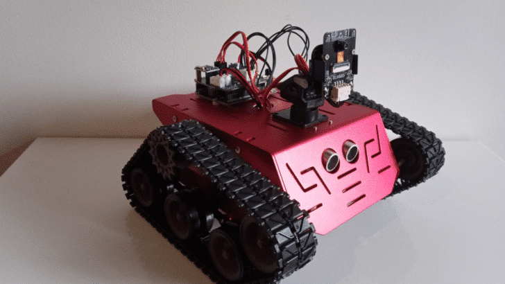
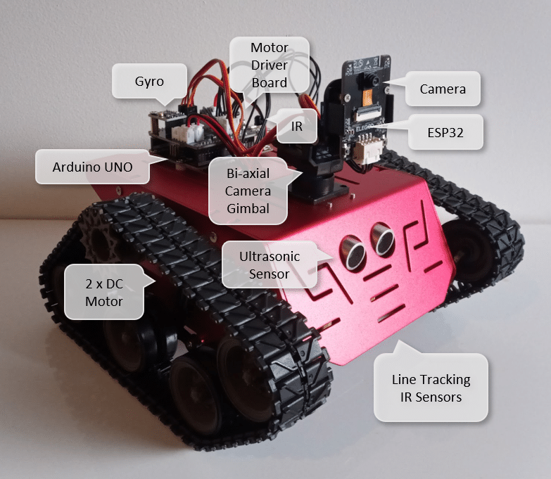
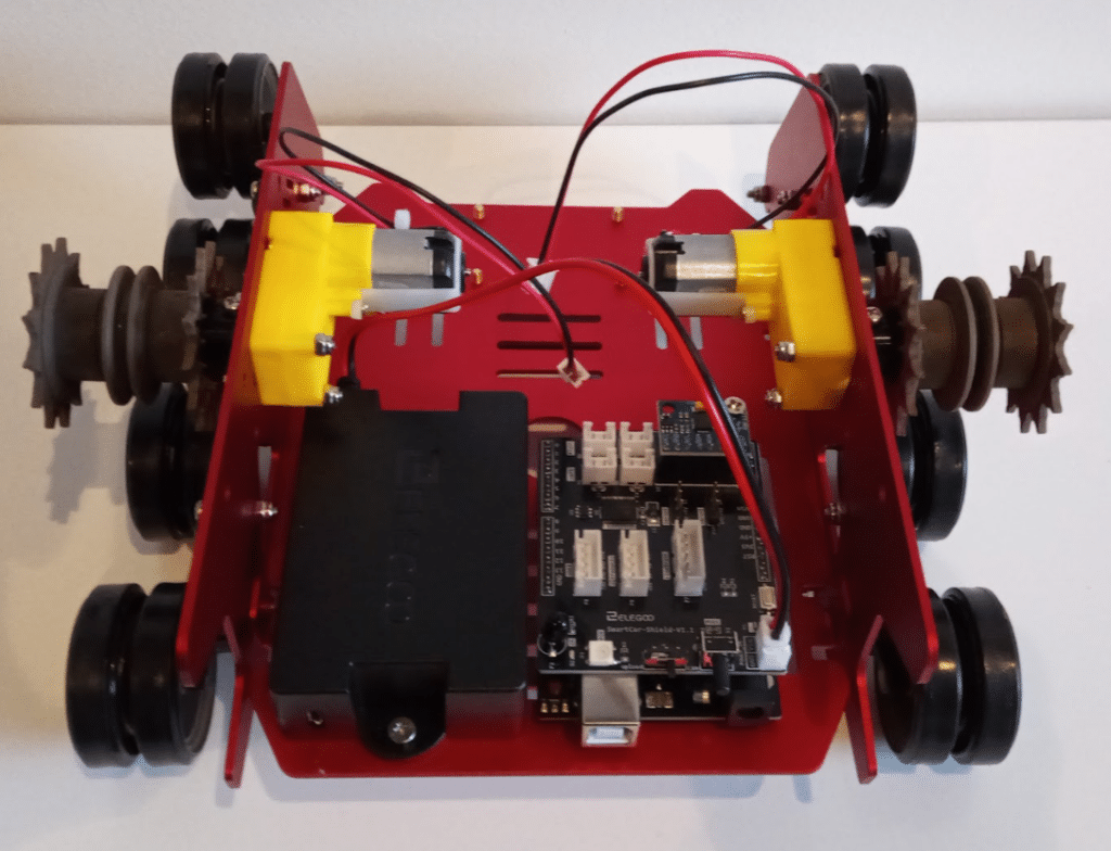
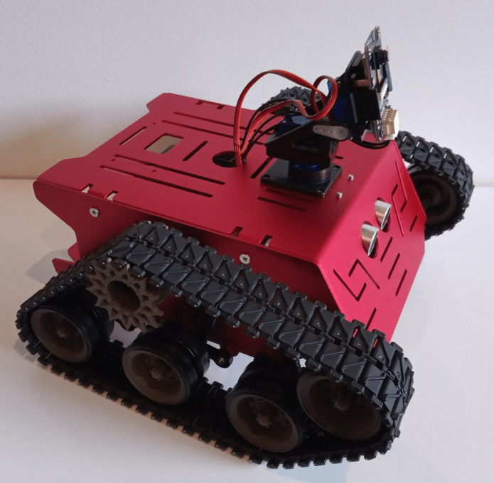
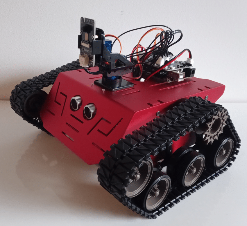
Below you can see a picture of the ELEGOO Conqueror Robot Tank with its main components annotated. The battery and the two DC motors for propulsion are inside, while the Line Tracking Module is on the underside and also not visible in this image.
Below the main features of the robot:
- Controller: Arduino UNO R3
- Programming Software: Arduino IDE, ElegooKit
- Input: Infrared Sensors, Ultrasonic Sensor, Buttons
- Output: Motor, Servo Gimbal, RGB LEDs
- Voltage: 7.2~8.4v (7.4v Lithium Battery Pack)
- Battery Life: 2 hours (Line-tracking Mode)
- Distance Measuring Method: Ultrasonic Ranging Sensor
- Motor Driver: Dual-channel DRV8835 Driver Chip
- Tracking Method: Infrared Tracking
- Motor: DC Motor 1:48
- Communication: UART / WIFI
- Camera: OV2640
- WIFI Mode: ESP32-WROVER
- Two degrees of freedom gimbal (SG90 Servos)
Step 1: Material List
The robot kit comes with a lot of parts but they are nicely labelled and the instructions are good. Note, however, that some screws are very small. You may need tweezers and definitely a pair of good eyes.
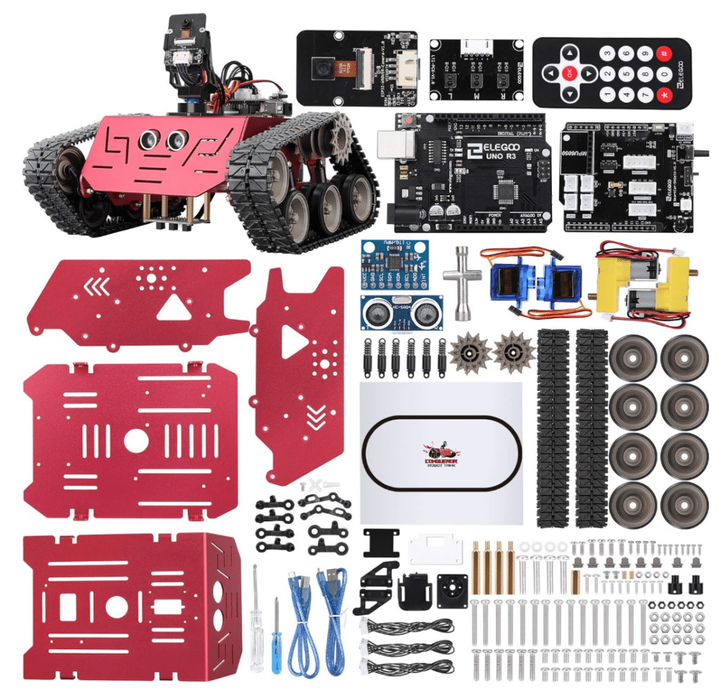
Don’t worry if you have parts left over at the end of the build. The bags contain spare parts, which is very nice should you drop and loose one them. Happens all the time : (
In the next sections, I will follow the numbered steps of the manual that came with the kit but will give you additional details and suggestions.
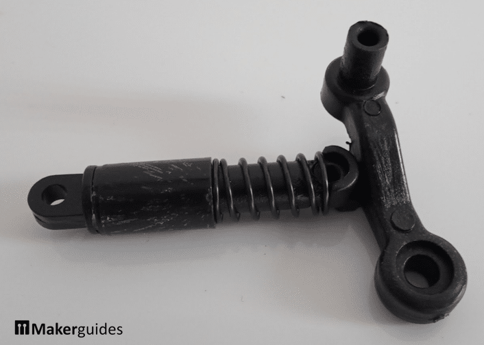
Step 2..3: Left & Right Rocker
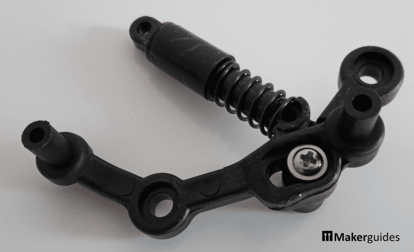
The first building steps; the assembly of the dampeners and wheel rockers is actually the most difficult part of the entire build. The parts are of a complex shape and the depictions of the parts is fairly small. Below you will find bigger images of the assembled parts.
The first one is the wheel suspension that is composed of a rocker and a dampener:
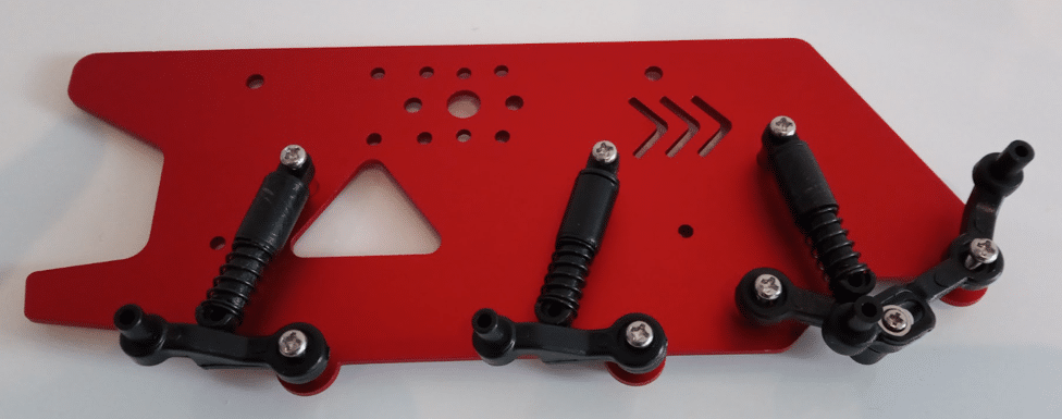
The second wheel suspension is composed of two rockers and one dampener. Don’t tighten the screw that links the two rockers! The rocker should slide freely in the slot without wiggling though.
Step 4..5: Left & Right Board
In Steps 4 and 5 you are asked to attach the wheel suspensions to the sideboards.
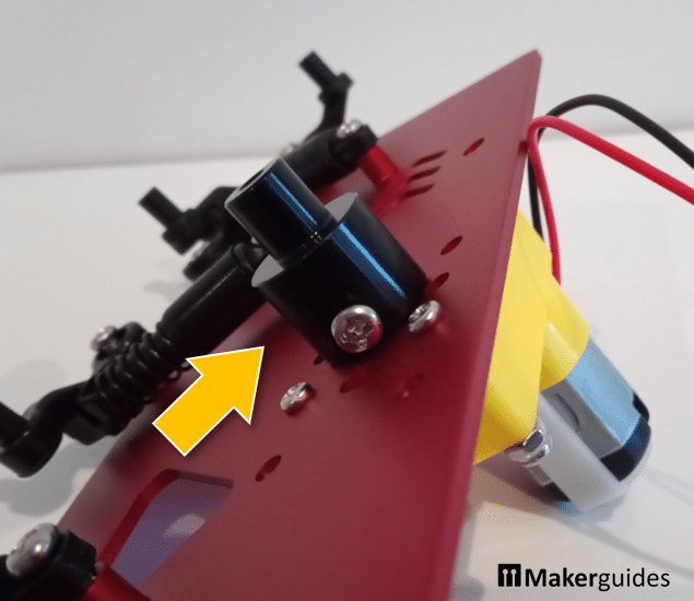
When you screw the wheel suspensions to the sideboard don’t tighten the locknuts at the back just yet. See the image below, where I barely screwed the locknuts in:
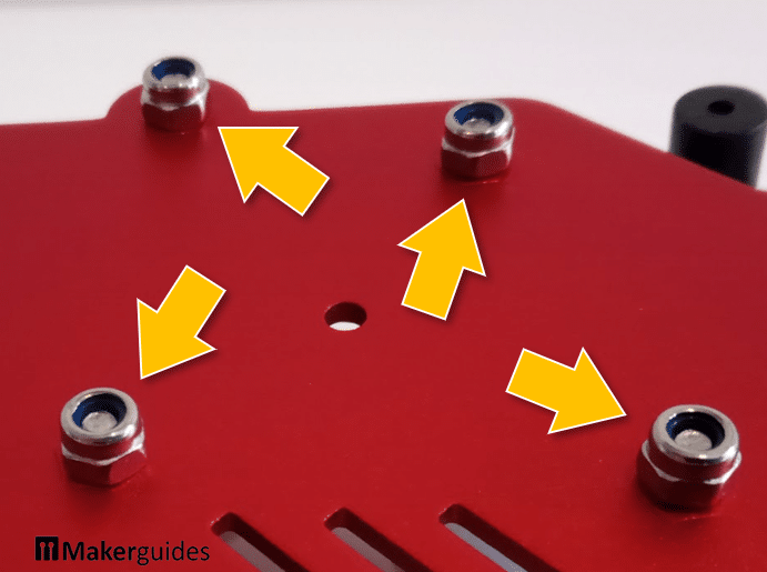
It is better to check the assembly first and leave this to the last possible moment. Once the locknuts are tightened it is sometimes very difficult to loosen them again. I made this mistake in other builds and since then try to avoid this mistake ; )
Step 6: Motor
In Step 6 you mount the motors to the side boards. Watch out for the orientation of the motors. They can be mounted in two directions. The gearbox (yellow arrow) should point to the end of the robot (away from the arrow shaped slots) for both side boards as shown in the picture below.
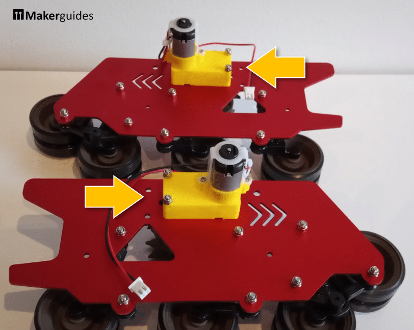
The pictures above have the wheels assembled. This steps actually comes later. But I had to fix the orientation of my motor on the right board. It was colliding with the Gyro Module on the Extension Board.
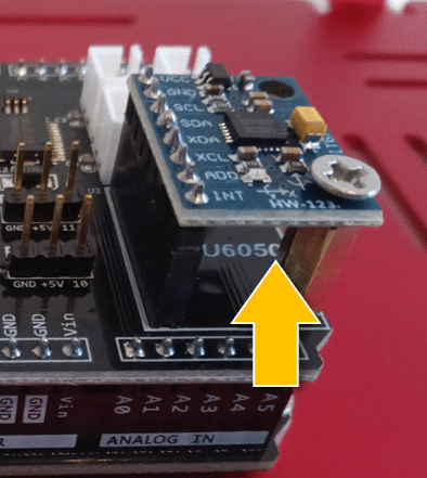
If you find the motor to get very close to the Gyro board, you have mounted the right motor in the wrong orientation as well.
Step 7: Driving Wheel
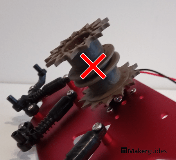
Step 7 is when you are asked to attach the driving wheel. I suggest you mount the coupling but do not screw on the Driving Wheel yet.
It will be much easier to put the tracks on the wheels then. The picture below shows the side board with the driving wheel already attached because I followed the instructions but then decided to take it off to simplify the mounting of the tracks.
Step 8: Other Wheels
Before attaching the other wheels in Step 8, now is a good time to tight the screws and locknuts for the wheel suspensions. Take your time with this. They need to be just tight enough to allow the rockers to move freely but without any wiggle.
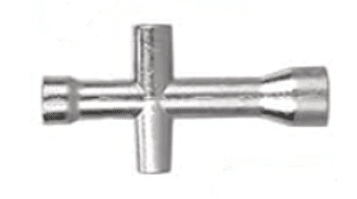
The kit actually comes with a tool (Cross Sleeve) that allows you to hold the locknuts while tightening the screws. I completely missed that and used pliers. Don’t do that ; )
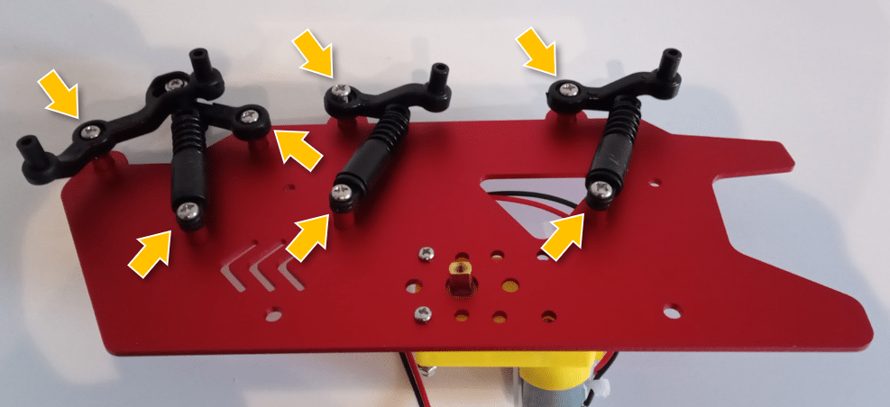
The wheels are attached to the wheel suspensions with small screws (see picture below). Don’t tighten these screws for wheels too much! There is not much feedback about when they are completely screwed in and the wheel will remain wiggly. That is okay.
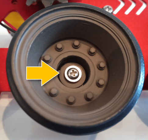
Also support the rocker from the back when screwing in the screws and pushing in the wheel caps. Otherwise you might break the wheel suspension.
This picture shows the complete assembly with driving wheel, but as I said I actually would attach the driving wheel later to simplify the mounting of the tracks.
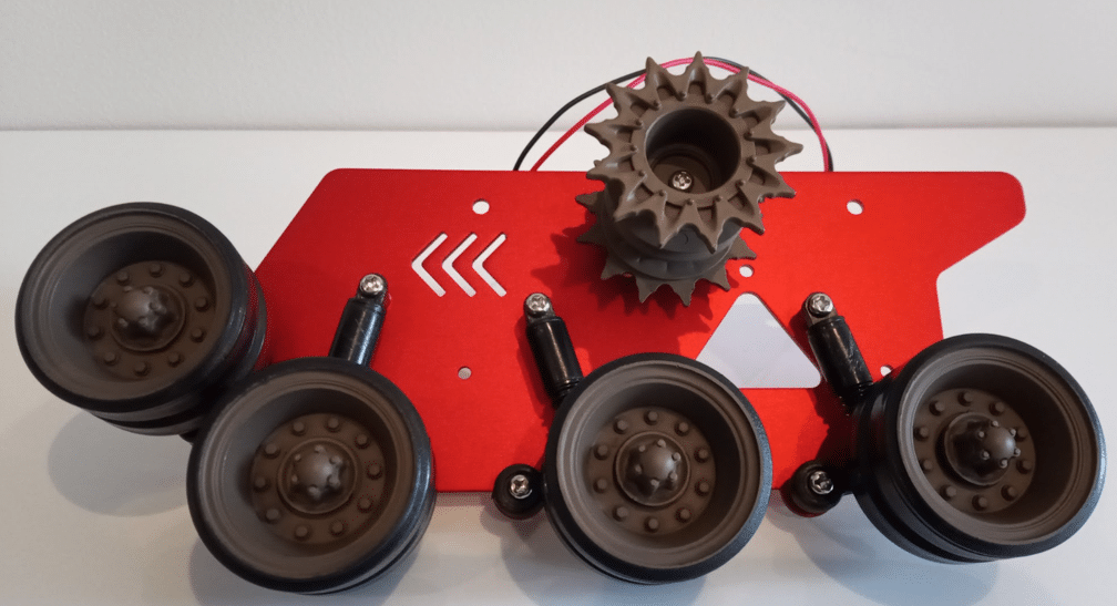
Now you can try out the wheel suspension. When pressing down the wheels on the ground the rocker and dampener of the wheel suspension show move freely but without any wiggle.
Step 9/11: Arduino Board
In Step 9 you will mount the Arduino Board on the frame. See picture below.
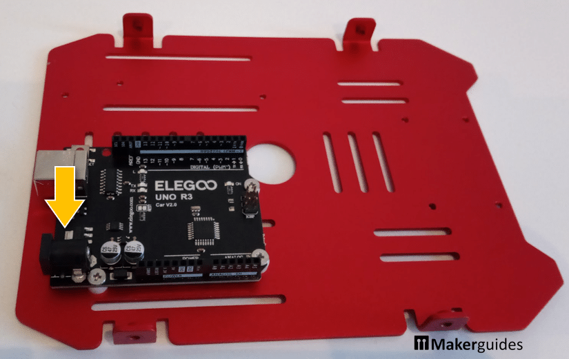
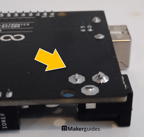
However, I noticed that the pins of the 9V connector (marked by the yellow arrow) on the backside of the board get very close to the base plate. In the picture below you can see the long pins of the 9V connector on the backside of the board
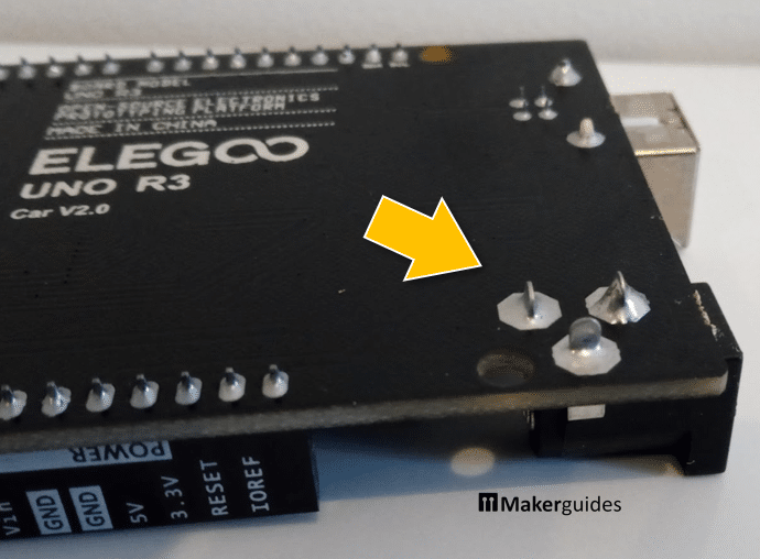
They get a bit too close to the metal frame for my taste. So I shortened those pins to make sure they do not touch the frame.
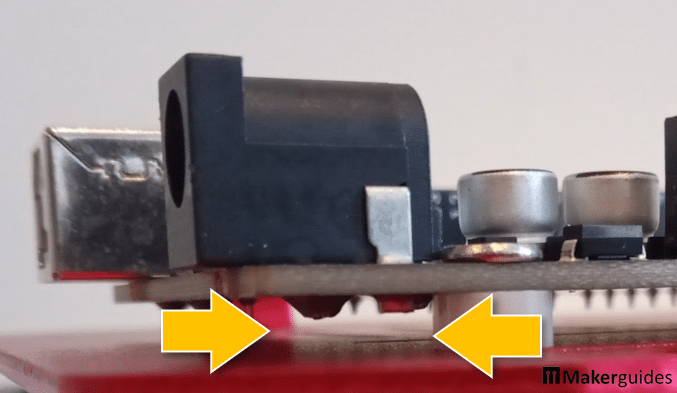
With that there is now sufficient space between the pins and the base plate (see image below). Alternatively, you can add a piece of sticky tab to make sure the pins don’t make contact with the metal frame. But cutting them is safer.
By the way, if you have problems with the separation pillars moving around, use some glue to fix them in place first, before screwing the board on.
Alternate Assembly
At the very end (Step 11) the instructions manual suggests an alternative assembly. Instead of mounting the Arduino board to the base plate at the bottom of the robot it can also be mounted to the top. See the picture below for comparison. Left the bottom mount and right the top mount.
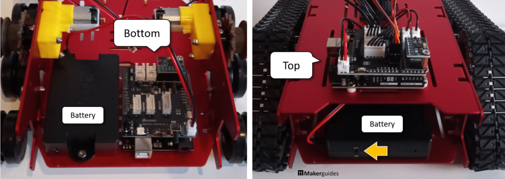
The top mount is actually the better position for the board. It allows easy access to the connectors, so you can fix connection errors more easily. And more importantly, the IR diode that is used to control the robot via the little remote is then visible from all directions. With the board mounted at the bottom you will have issues controlling the robot.
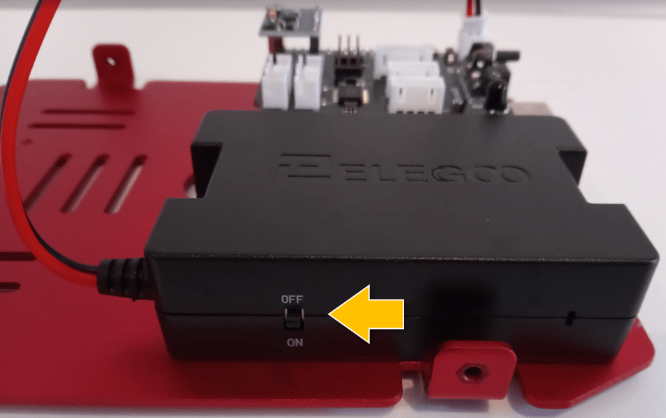
The steps in the next sections show the board in the bottom position, since that is how I assembled the robot first. I later switched to the top mount position, which is easy enough. Just watch out that the battery box is rotated by 90 degrees and that the on/off switch is accessible from the back (yellow arrow)
Step 10: Extension Board
In Step 10, you attach the Gyro Module and attach the Extension Board to the Arduino. Just make sure that you don’t bend the pins, when plugging in the Gyro Module and that the Extension Head and the Arduino board are correctly aligned.
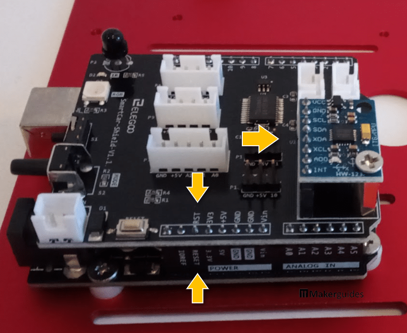
I look for the pins marked RST and RESET to make sure that the Extension Head is properly plugged into the Arduino Board.
Step 11/21: Battery Box
As mentioned above, there is two ways to mount the battery box. If the Arduino board is mounted on the bottom, the battery box is mounted sideway. Make sure that the on/off switch is pointing to the outside in this case.
Otherwise, you won’t be able to switch on the robot from the outside, once the build is complete.
If you go with the top-mount for the Arduino board, the battery box is rotated by 90 degrees. Again, make sure that the on/off switch is pointing outwards; to the back of the robot.
Step 12: Line Tracking Module
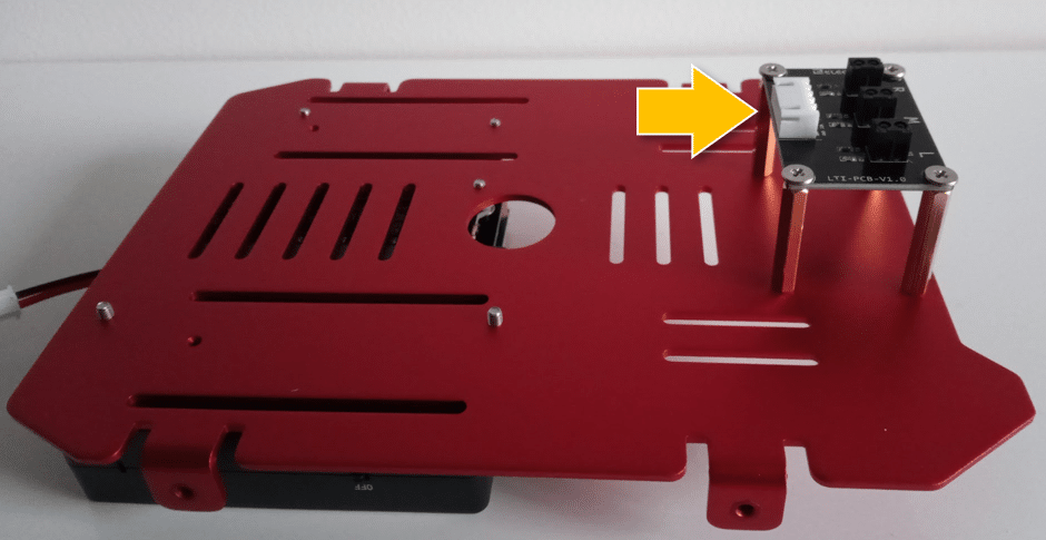
Attaching the Line Tracking Module to the underside of the base plate is easy. Just make sure that the connector is pointing inwards.
Step 13: Camera Bracket
When you assemble the Camera Gimbal with the servos you probably will encounter a problem with the base plate.

In noticed that two screw holes in the Bracket Base don’t line up with the Cross Arm. Use the ones that do align first to fix the Cross Arm in place. Then screw the other two in in a slight angle. That worked for me.

Step 14, 15: Wiring Diagram & Servo Calibration
Step 14 is just a picture of the Wiring Diagram. And Step 15 is the Servo Calibration. No comments on those Steps from my side.
Step 16: Ultrasonic Module
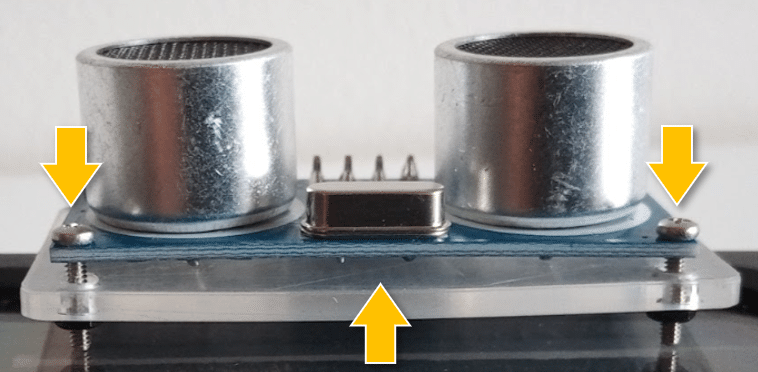
When you attach the Ultrasonic Module to its bracket in Step 16 watch out. There are no separation pillars between the Module and the bracket. If you tighten the screws too much the board will bend or even break!
Step 17: Camera Module
Assembling the Gimbal system for the camera is a bit fiddly and you need to be extra careful not to break anything. Snapping the Camera Module in its bracket takes some force.
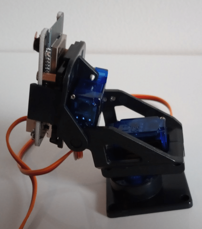
Especially watch out for the connection between servo and base bracket. It can break or deform easily. I think, I will 3D print a ring for better mechanical stability.
Step 18: Side Panels
Attaching the Side Panels to the Base Plate is easy. This is a good time to check the wheel suspension again. The robot should be nice and bouncy on the suspensions but without any wiggle. Roll it around and push it down a bit.
Step 19: Wiring
As for the wiring: some of the white connectors are hard to plug in. Try to wiggle them in and provide some support on the backside of the board or robot. Don’t force the connectors in, while the robot is resting on its wheels. You may break the wheel suspension!
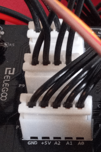
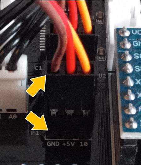
The white connecters go in only in one direction. You can’t get that wrong. The servo connecters, however are not protected in this way. Make sure that the brown cable is connected to the pin marked GND (Ground)!
Step 20: Top plate and tracks
In Step 20, we mount the tracks and attach the Top plate. As mentioned before, put the tracks on without the driving wheel. Then insert the driving wheel and screw it on. This way, mounting the tracks is easy.

Look our for the orientation of the tracks. They have a pattern and if you want the robot to look nice, the tracks on both sides should match.
Screwing on the top plate is easy. Just make sure that you don’t kink, break or squeeze cables. After that you have a nice, little robot.
Ready for test drive? Grab the remote, remove the plastic piece (battery otherwise disabled), switch on the robot and control its movement with the arrow keys on the remote. If that works, congratulation! Everything is connected and assembled correctly.
If you see a red light, your battery might not be charged and you have to charge it first. Mine, however, was fully charged.
Step 21: Alternate assembly
Step 21 shows the instructions for an alternate assembly. I mentioned this before and recommend this alternate assembly. It gives better access to the electronics and most importantly allows the IR diode to receive the IR signal of the remote from all directions.
With the first assembly, the robot looses the IR signal when it turns and then stops. I would rewire the IR diode and attach to the top of the top plate for better reception, if you go for bottom mounted version.
I started with the bottom mounted version but then I tried the second version with board on top and liked it much better. It looks cooler and gives you plenty of space in the body for additional electronics and a potentially a larger battery.
Conclusion
Building this robot is fun. The instructions are good and the bags with the parts are nicely labelled. The entire build, with a leisurely pace, took me about 3 and half hours. But I was also taking a lot of pictures between steps.
I didn’t have any real issues apart from mounting one motor in the wrong orientation first, because I didn’t look at the instructions carefully enough. The misaligned holes in base bracket for the camera gimbal threw me off for a minute, especially since the screws are tiny. But in the end it worked out.
The metal frame is of high quality and provides an excellent basis to extend the robot with extra functionality. The slots in the frame will come in handy to screw on additional parts.
There are few things, I intend to improve. First, I want to connect the IR diode to a wire and attach it to flexible rod, so that it works as an antenna. That should result in better IR remote control of the robot. The range of the little remote is rather limited (a few meters). I might change the code and use a different remote with a larger range.
Second, as mentioned, the connection of the Servo with the Base Bracket as part of the Camera Gimbal is weak. I am going to 3D-print a ring that I will insert into the base plate for better mechanical stability.
Finally, I think I am going to replace the closed battery module with an open case, so that I can charge the batteries externally or swap out the batteries.
Luckily we are makers, and can do this things ourselves ; )
Stefan is a professional software developer and researcher. He has worked in robotics, bioinformatics, image/audio processing and education at Siemens, IBM and Google. He specializes in AI and machine learning and has a keen interest in DIY projects involving Arduino and 3D printing.