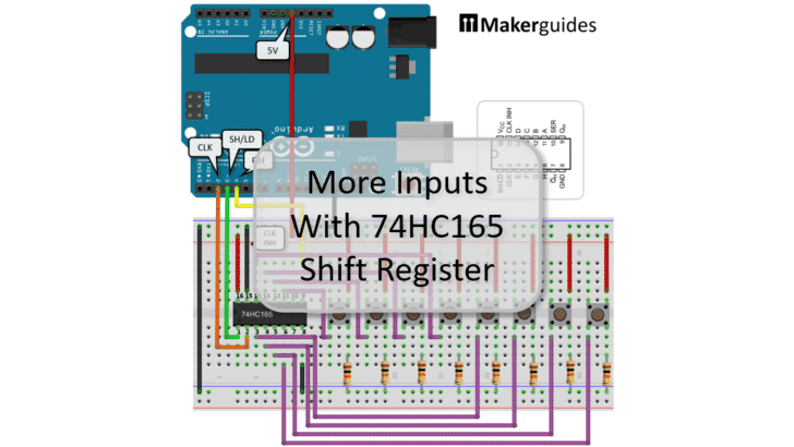
In this tutorial I will show you how to add more inputs with the 74HC165 Shift Register to your Arduino or ESP8266/ESP32.
The popular Arduino UNO has 14 GPIO pins you can use to input (or output) data. Often this is a sufficient but sometimes you need more. You could buy a more expensive Arduino such as an Arduino Mega with 54 GPIO pins or a GPIO expander board. But the cheapest way is to use a Shift Register such as the 74HC165.
The 74HC165 provides 8 inputs, uses up only 3 pins from your Arduino and can be chained to read as many inputs as you like. The only disadvantage is that it is slower than using Arduino GPIO pins directly. Common applications are the decoding of keyboards or if you have a multitude of digital sensors.
Let’s start with the required parts before looking at the function of the 74HC165 Shift Register in more detail.
Required Parts
I used an Arduino Uno for this project but any other Arduino board, or ESP8266/ESP32 board will work just as well. I listed a set of push buttons but for my actual build, I used a DIP switch, since it is more compact. But push buttons are fine as well.

Arduino Uno

Dupont Wire Set

Breadboard

USB Cable for Arduino UNO
74HC165 Shift Register

Push Button
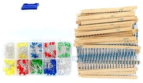
Resistor & LED kit
Makerguides.com is a participant in the Amazon Services LLC Associates Program, an affiliate advertising program designed to provide a means for sites to earn advertising fees by advertising and linking to products on Amazon.com. As an Amazon Associate we earn from qualifying purchases.
Function of the 74HC165 Shift Register
The 74HC165 is a 8-bit parallel-load shift register that reads 8 digital inputs in parallel and then serially outputs them on a single pin. It needs a clock input, to time the shifting of the 8 digital inputs to the serial output, and another signal to control the loading of the input data.
That means with three pins and one 74HC165 you can read up to 8 digital inputs. However, you can also daisy-chain multiple 74HC165s and then can read an essentially unlimited number of digital inputs, still using only three pins on your microcontroller!
Functional Block Diagram
The picture below shows the Functional Block Diagram of the 74HC165 Shift Register. You can see the 8 parallel digital inputs (A…H) at the top. The serial output QH and its complement Q̅H are on the right. And in the center you find the latches (flip-flops) the input data is loaded into.
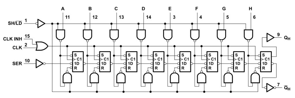
The control inputs are on the left. SH/L̅D̅ enables the 8 digital inputs when pulled to low. CLK (or CLK INH), shifts the data one by one to the serial output QH . And SER is serial input used when chaining multiple 74HC165 Shift Registers.
Logic diagram
The following image shows the logic diagram of the process. The CLK signal times the shifting of the digital inputs (A…H) to the serial output QH and its inverse Q̅H.
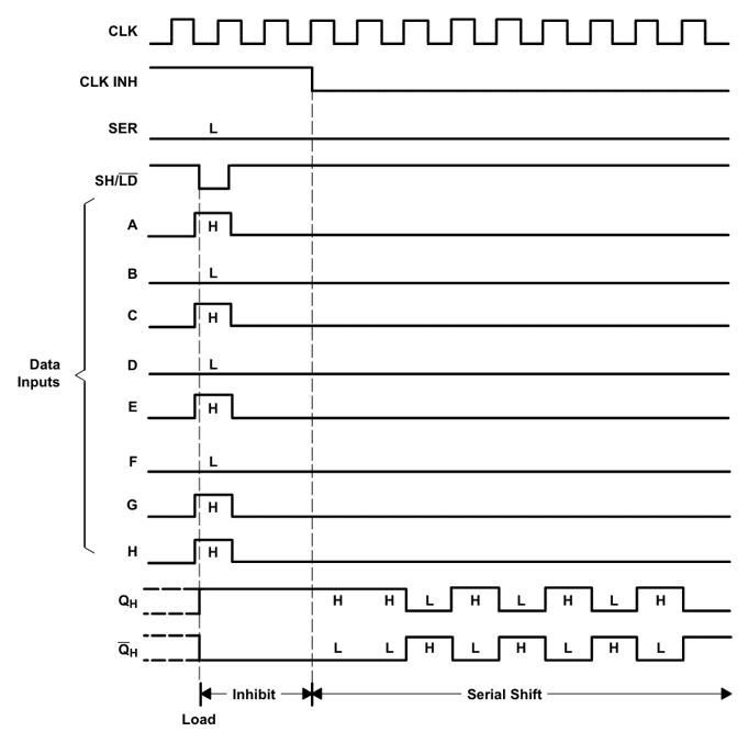
The clock signal is disabled as long as clock-inhibit (CLK INH) is high. Similarly for loading the digital inputs the SH/L̅D̅ needs to go to low. SER is only used when chaining multiple Shift Registers.
In summary, to shift the 8 digital inputs A…H to the serial output QH we need to perform the following steps.
- Set SH/L̅D̅ to low to load the data
- Set SH/L̅D̅ back to high
- Repeat 8 times the following steps
- Set CLK to high to shift the data
- Set CLK back to low
CLK INH is not needed and we can keep it low the entire time. Also, when using only a single 74HC165 Shift Register the SER input is not used.
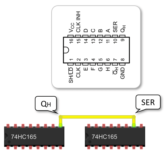
Pinout
In the picture below you will find the Pinout of the 74HC165 Shift Register. Power is supplied via VCC and GND. The supply voltage VCC can range between 2V and 6V, and the output voltage on the QH pin is determined by VCC.
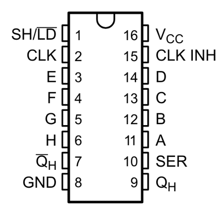
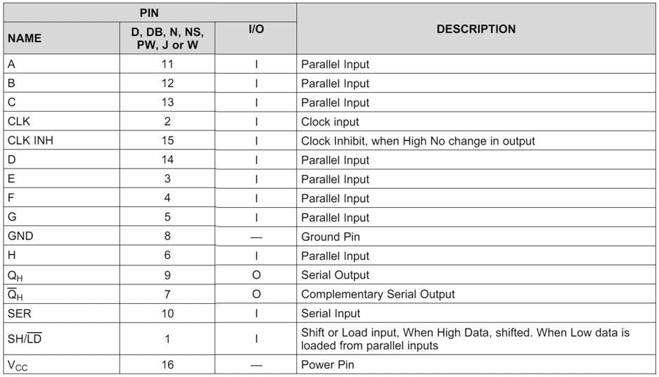
The purpose of the other pins we have already discussed above but the following table summarizes the functions of all pins. Additional details can be found in the Datasheet for the 74HC165 Shift Register.
In the next section, we will connect the 74HC165 Shift Register to an Arduino.
Connecting the 74HC165 Shift Register to Arduino
To keep things simple, we are connecting the 74HC165 to the Arduino without any signals on the data input pins A…H first. The picture below shows the wiring of this first step.
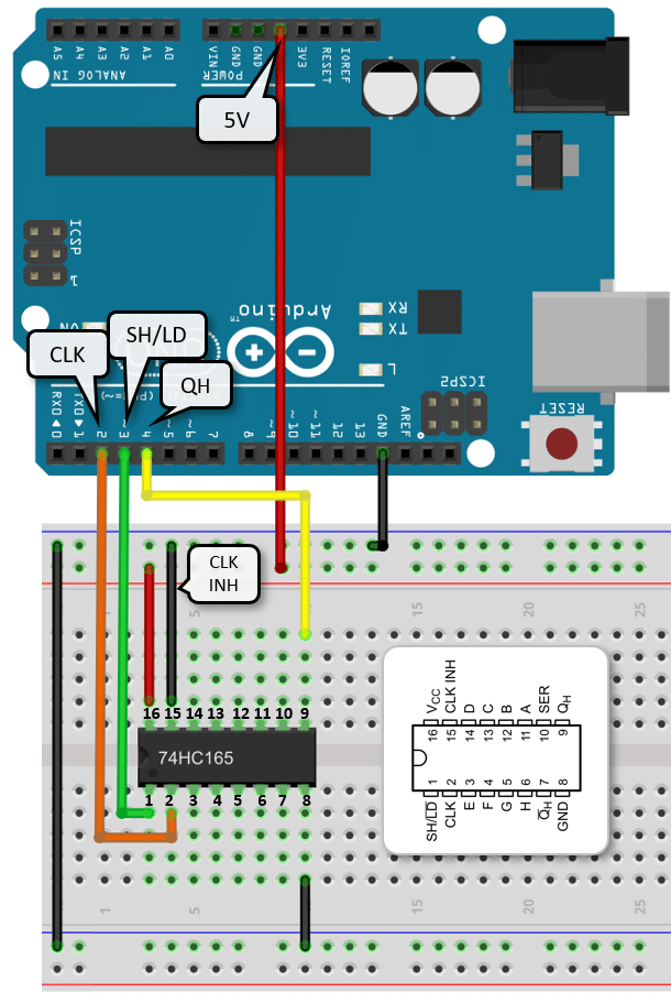
Let’s start with the power supply connections. Run a black wire from the GND pin of the Arduino to the negative power rail of the bread board. Then use a red wire to connect the 5V from the Arduino to the positive power rail. Next we connect the two negative power rails on the bread board with a black wire. We don’t use the second positive rail, so we don’t need a connection there.
Now, let’s connect the power for the 74HC165. Connect pin 8 (GND) of the 74HC165 to the negative power rail (black wire) and pin 16 (VCC) to the positive power rail (red wire).
Finally, the signal wires. We don’t use CLK INH on pin 15 and therefor connecting it directly to the negative power rail (black wire). SH/L̅D̅ on pin 1 gets connected to pin 3 on the Arduino (green wire). The CLK signal on pin 2 gets connected to pin 2 on the Arduino (orange wire). And the serial output QH on pin 9 gets connected to pin 4 (yellow wire).
And these are the connections needed to control the 74HC165 and retrieve data from it. In the next section we are connecting some buttons as digital inputs to the input pins.
Connecting Buttons to the 74HC165 Shift Register
We could connect any kind of digital signal to the input pins (A…H) of the 74HC165. But for trying it out, we will connect some buttons. And we will start by connecting a single button first. The wiring diagram below shows the same circuit as above plus the wiring for a single button.
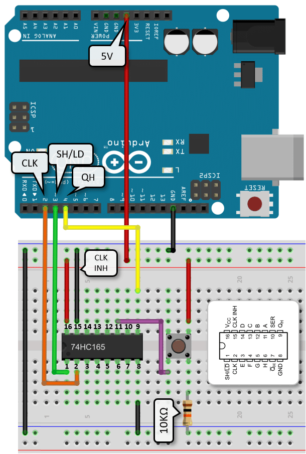
The button is connected in a pull-down configuration with a 10KΩ resistor. That means when the button is pushed the signal gets pulled to ground. To achieve this we connect one pin of the button to the positive power rail (red wire) and the opposite pin to the negative power rail via the 10KΩ resistor.
The output of the button is connected to the digital input A on pin 11 of the 74HC165 (purple wire). Note that the other end of the purple wire is connected to the same pin as the resistor, since the internal wiring of the button is as follows:
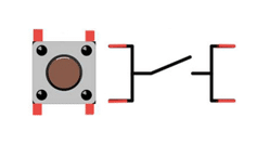
Make sure to insert the button in the correct orientation into the breadboard. And if you need more information on push buttons, have a look at our tutorial How to use a Push Button with Arduino.
Note that you could also wire the button in a pull-up configuration but the output on QH would then be inverted. To compensate for that you could use the complementary output Q̅H to invert it again or handle the inversion in code.
Connecting multiple buttons
The wiring diagram below shows you how to connect 7 more buttons to create signals for all the 8 digital inputs A…H of the 74HC165. They are all wired in the same way as the single button above, just the outputs are connected to the other inputs B…H of the 74HC165 (purple wires).
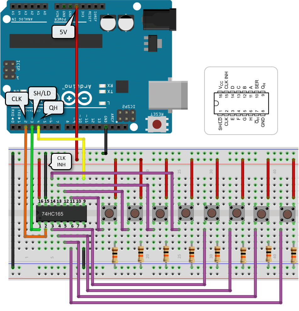
As you can see that is a lot of wires ; ) Let’s have a look what we need to do to read the states of these buttons.
Code to read Buttons with the 74HC165 Shift Register
In this section we read the state of the buttons connected to the 74HC165. The code is simple and follows the steps defined by the logic diagram of the 74HC165:
- Set SH/L̅D̅ to low to load the data
- Set SH/L̅D̅ back to high
- Repeat 8 times the following steps
- Set CLK to high to shift the data
- Set CLK back to low
Have a look at the complete code below first and then we will discuss its details.
const int dataPin = 4;   // QH
const int clockPin = 2;  // CLK
const int latchPin = 3;  // SH/LD

void setup() {
  Serial.begin(9600);
  pinMode(dataPin, INPUT);
  pinMode(clockPin, OUTPUT);
  pinMode(latchPin, OUTPUT);
}

void loop() {
  // Load input bits into latches
  digitalWrite(latchPin, LOW);
  digitalWrite(latchPin, HIGH);

  for (int i = 0; i < 8; i++) {
    int bit = digitalRead(dataPin);
    Serial.print(bit ? "1" : "0");

    // Shift out the next bit to QH
    digitalWrite(clockPin, HIGH);
    digitalWrite(clockPin, LOW);
  }

  Serial.println();
  delay(1000);
}
In the code snippet above, we are reading 8 digital input bits from the 74HC165 Shift Register and printing them out every second.
Constants and Variables
We start by defining the constants dataPin, clockPin, and latchPin which represent the pins connected to the data (QH), clock (CLK), and latch (SH/LD) pins of the 74HC165 Shift Register. Note that you can use other Arduino pins as well. Just make sure the wiring and the code match.
const int dataPin = 4;   // QH
const int clockPin = 2;  // CLK
const int latchPin = 3;  // SH/LD
Setup function
In the setup() function, we initialize the serial communication at a baud rate of 9600. We also set the dataPin as INPUT and the clockPin and latchPin as OUTPUT since we will be reading data from the data pin and controlling the clock and latch pins.
void setup() {
  Serial.begin(9600);
  pinMode(dataPin, INPUT);
  pinMode(clockPin, OUTPUT);
  pinMode(latchPin, OUTPUT);
}
Loop function
In the loop() function, we first load the input bits into the latches of the shift register by toggling the latch pin.
void loop() {
  digitalWrite(latchPin, LOW);
  digitalWrite(latchPin, HIGH);

  ...
}
Then, we iterate over each of the 8 bits, read their values from the data pin, print them out (as ‘1’ or ‘0’), and shift out the next bit by toggling the clock pin. Finally, we add a delay of 1 second between each of the reading cycles.
void loop() {
  digitalWrite(latchPin, LOW);
  digitalWrite(latchPin, HIGH);

  for (int i = 0; i < 8; i++) {
    int bit = digitalRead(dataPin);
    Serial.print(bit ? "1" : "0");

    digitalWrite(clockPin, HIGH);
    digitalWrite(clockPin, LOW);
  }

  Serial.println();
  delay(1000);
}
With this code and circuit you can now read 8 digital inputs using just three pins of your Arduino. And, of course, this works the same for an ESP8266 or ESP32. If you run this code you should see an output like this on your Serial Monitor.
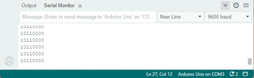
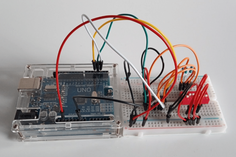
The actual bit pattern will depend on the buttons you push while running the program. As I mentioned, I actually used a DIP switch and wired up only the first four switches to test the circuit and code. The picture below shows my breadboard with the circuit.
With the circuit and code above you can read up to 8 digital inputs. If you need even more inputs, you can chain multiple 74HC165 Shift Registers. How that is done, is the topic of the next section.
Chaining of 74HC165 Shift Registers
You can connect the serial output QH of one 74HC165 Shift Register to the serial input SER of another 74HC165 Shift Register to chain them together. This allows you to read 16 instead of 8 digital inputs.
And you don’t have to stop there. You could keep going chaining as many as you like; allowing you an essentially arbitrary number of digital inputs. And the best news is all those 74HC165 Shift Register are controlled via the same three pins.
The wiring diagram below shows how to connect 16 buttons as inputs to an Arduino using two 74HC165 Shift Registers. It looks complicated but is just a duplication of the wiring above.
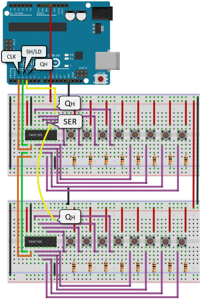
Note that the CLK and SH/LD of the 74HC165’s are connected in parallel and the only difference compared to the wiring of a single is 74HC165 is the chaining via the QH and the SER pins.
Code for reading from chained 74HC165 Shift Registers
The code for reading data from two chained 74HC165 Shift Registers is a simple extension of the code for reading from a single 74HC165 Shift Register. See below:
const int dataPin = 4;   // QH
const int clockPin = 2;  // CLK
const int latchPin = 3;  // SH/LD

const byte numBits = 16;

void setup() {
  Serial.begin(9600);
  pinMode(dataPin, INPUT);
  pinMode(clockPin, OUTPUT);
  pinMode(latchPin, OUTPUT);
}

void loop() {
  digitalWrite(latchPin, LOW);
  digitalWrite(latchPin, HIGH);

  for (int i = 0; i < numBits; i++) {
    int bit = digitalRead(dataPin);
    Serial.print(bit ? "1" : "0");

    digitalWrite(clockPin, HIGH);
    digitalWrite(clockPin, LOW);
  }

  Serial.println();
  delay(1000);
}
We just add a constant numBits that allows us to define how many bits we want to read. In case of a single single 74HC165 Shift Register that would be 8 bits. If we use two Shift Register we can read 8 * 2 = 16 bits, and so on.
Using the ArduinoShiftIn to read from 74HC165 Shift Register
If you don’t want to write your own code to handle the control of the 74HC165 Shift Register, there is nice little library to help you. It is named ArduinoShiftIn but should work on a ESP32 or ESP8266 as well. It is especially handy when you chain multiple 4HC165 Shift Registers and want to read the input data into a single variable.
To install the ArduinoShiftIn library go to the ArduinoShiftIn github repo, download the Zip file and then add it your Arduino IDE via: Sketch > Include Library > Add .ZIP > select the zip file.
The following code example is from one of the ArduinoShiftIn examples and demonstrates how to read from two 74HC165 Shift Registers:
#include "ShiftIn.h"

ShiftIn<2> shift;  // 2 = two 74HC165

void setup() {
  Serial.begin(9600);
  // pLoadPin, clockEnablePin, dataPin, clockPin
  shift.begin(8, 9, 11, 12);
}

void displayValues() {
  for(int i = 0; i < shift.getDataWidth(); i++)
    Serial.print(shift.state(i));
  Serial.println();
}

void loop() {
  if(shift.update())
    displayValues();
  delay(1);
}
You have to specify the number of chained 74HC165 Shift Registers when declaring the shift object:
ShiftIn<2> shift;
In the setup function we establish the serial communication and define the pins to control the 74HC165 Shift Register.
void setup() {
  Serial.begin(9600);
  // pLoadPin, clockEnablePin, dataPin, clockPin
  shift.begin(8, 9, 11, 12);
}
Note that the ArduinoShiftIn library uses all four pins, while in the code and circuit examples we connected CLK INH to ground and did not use it. Here you have to define the clockEnablePin (= CLK INH) and have to connect it.
The function displayValues(), as it name says, show the input values read from the v
void displayValues() {
  for(int i = 0; i < shift.getDataWidth(); i++)
    Serial.print(shift.state(i));
  Serial.println();
}
The function shift.getDataWidth() gets the number of bits to read. You don’t have to multiply the number of shift registers by 8 by yourself. And shift.state() returns the status of the i-th input.
Finally, the loop function. It calls displayValues(), but only if the state of any of the inputs has changed, which is signalled by the shift.update() function.
void loop() {
  if(shift.update())
    displayValues();
  delay(1);
}
Note, however, that shift.update() is not even-driven and simply polls the state of the 74HC165 Shift Registers with the speed of the loop – in this example with a delay of 1 microsecond.
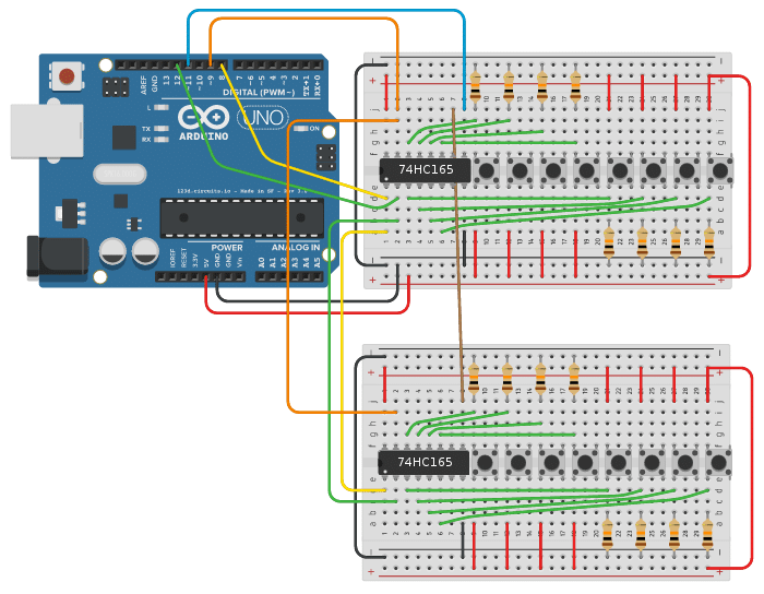
The picture below shows the wiring needed to run this code. It is essentially the same as before, with the difference that different control pins are used and that you have to connect the CLK INH to the Arduino.
In summary, the ArduinoShiftIn library simplifies the code for reading inputs from chained 74HC165 Shift Registers but has the slight disadvantage that it occupies one more GPIO pin (CLK INH). However, if you chain many (up to 8) Shift Registers that usually is not an issue, since you have plenty of additional inputs.
Conclusions
In this tutorial you learned how to use the 74HC165 Shift Register to add an arbitrary number of digital inputs to your microcontroller. The circuit and code shown used an Arduino but it will work on an ESP32 and ESP8622 as well.
In contrast to GPIO expanders that can read and write analog inputs and outputs, the 74HC165 Shift Register is limited to reading digital inputs only. However, the 74HC165 is generally much cheaper then a GPIO expander board.
If you want to write many outputs as well have a look at our tutorial More Arduino Outputs With 74HC595 Shift Register, which uses just another type of Shift Register to write data instead of reading them.
If you need analog inputs and outputs a GPIO expander such as the MCP23017, for instance, is the better choice. Have a look at our tutorial Using GPIO Expander MCP23017 With Arduino, for more information on this.
And now, feel free to build projects with massive numbers of inputs and outputs ; )
Frequently Asked Questions
Here are some frequently asked questions about using the 74HC165 Shift Register.
Q: What is a 74HC165 shift register?
A: The 74HC165 is a parallel-in/serial-out shift register that allows you to expand the number of digital inputs on your Arduino using only a three pins.
Q: How many inputs can the 74HC165 shift register handle?
A: The 74HC165 shift register can handle up to 8 digital inputs, which can be useful for projects requiring multiple input devices.
Q: How do I connect the 74HC165 shift register to my Arduino?
A: You can connect the 74HC165 shift register to your Arduino by wiring the parallel inputs to your input devices and connecting the serial output pin to the Arduino’s digital pins.
Q: Can I daisy-chain multiple 74HC165 shift registers together?
A: Yes, you can daisy-chain multiple 74HC165 shift registers together to expand the number of inputs even further, allowing you to connect more input devices to your Arduino.
Q: What are the key benefits of using the 74HC165 shift register in Arduino projects?
A: The key benefits of using the 74HC165 shift register include expanding the number of inputs without using up all of your Arduino’s pins, simplifying wiring by reducing the number of connections needed, and enabling you to interface with multiple input devices efficiently.
Q: Can the 74HC165 shift register be used with other microcontrollers besides Arduino?
A: Yes, the 74HC165 shift register can be used with other microcontrollers that support digital input/output operations.
Q: Can I use the 74HC165 shift register in projects that require real-time input monitoring?
A: Yes, the 74HC165 shift register is suitable for projects that require real-time input monitoring, as it allows for fast reading of multiple digital inputs.
Q: Are there any common troubleshooting tips for working with the 74HC165 shift register?
A: Common troubleshooting tips for working with the 74HC165 shift register include double-checking the wiring connections, ensuring the correct clock and latch signals are provided, and verifying the input data format in your code to match the shift register configuration.
Stefan is a professional software developer and researcher. He has worked in robotics, bioinformatics, image/audio processing and education at Siemens, IBM and Google. He specializes in AI and machine learning and has a keen interest in DIY projects involving Arduino and 3D printing.