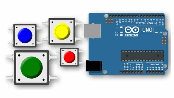

You will see push buttons everywhere. Just look around! TV remote, Microwave-oven, washing machine, laptops, calculators, and more!
This tutorial will show you how to interface push buttons to Arduino. You will learn how to use tactile switches and how the push button works.
By the end of this tutorial, you will be confident connecting push buttons (also known as momentary switches) to Arduino.
I will give a step-by-step guide to connect and read the status of push buttons.
You will get working Arduino examples to read the status of the button on the Arduino using polling method, interrupt methods, and more.
Let’s get started.
Components Needed To Use Arduino Serial Plotter
Hardware Components
- Arduino Uno Rev3 x 1
- Pushbutton x 1
- Dupont wire x 2
- Arduino USB cable (for powering and programming) x 1
- Breadboard x 1
Software
Makerguides.com is a participant in the Amazon Services LLC Associates Program, an affiliate advertising program designed to provide a means for sites to earn advertising fees by advertising and linking to products on Amazon.com. As an Amazon Associate we earn from qualifying purchases.
Quick Tip: Buy the push button switches, which come in through-hole PCB style. Through-hole style helps you to connect them on the breadboard easily.
What Is A Pushbutton?
Push-button, also known as a momentary switch, makes or breaks a connection. You can use the pushbuttons easily with Arduino.
Push buttons contain a spring mechanism inside. This mechanism allows the button to return to the previous state once you stop pressing them.
- Open State – When you are not pressing the push button
- Closed State – When you are pushing the button
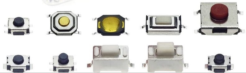
Pushbuttons come in various sizes and colors.
The basic operation is illustrated in the image below.
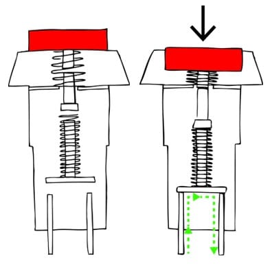
When you press the switch, you bring two pins in contact, thus closing a circuit.
Assume you connected one switch pin to the Microcontroller input pin and the other pin to the ground.
Then, by closing the switch, you bring the microcontroller pin to the ground. A microcontroller pin with an internal pullup enabled can detect this and take a preprogrammed action.
The common configuration of a push button is as shown below.
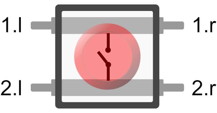
As you can see, either you can use the left side or the right side of the switch for the operation. The top and bottom rows are shorted internally, as shown in the image.
There are several types of switches you will come across. Each button has its unique applications. I have listed the most common push buttons below.
- Push to make switch – This is the most commonly used type of switch. The button brings two pins in contact when you press. Widely used to reset a microcontroller, doorbells, turn the light momentarily on, etc.
- Push to break switch – When you press these types of witches, they will break a connection. You use this type of switch when you have to break a circuit connection momentarily.
- Tactile switches – These are miniature-sized switches primarily used to mount on the PCBs. I will go for these switches when the button’s height has to be very minimal.
- Panel Mounted Switches – You can mount these kinds of switches on the panel, such as notice board, the front panel of equipment, etc
I will give a few critical parameters of a switch that you need to know before choosing one for your next project.
- Current Rating – The maximum current the switch can handle. The current rating is significant in applications that drive high-power LEDs in series with a button. The AC and DC ratings will be different.
- Voltage rating – This is the maximum voltage you can apply while operating the switch. AC and DC will have different ratings.
- Operating temperature – This is a common feature for any part you choose for your next project. Every switch will have equivalent series resistance, and once the current flows through it, power dissipation as heat will occur.
- Mechanical life – Number of pushes it can tolerate before the switch can fail. The failure can be permanent or intermittent.
Step-By-Step Instructions To Connect A Push Button To Arduino
The following sections will show you how to connect the pushbuttons with various input configurations with an Arduino.
Project 1: How To Connect Active-Low Push Button To An Arduino
What is an active-low configuration?
Active low configuration is when you press the push button, you either short the input pin the ground directly or through a very low-value resistor.
Arduino will read the pin status as zero (logic LOW).
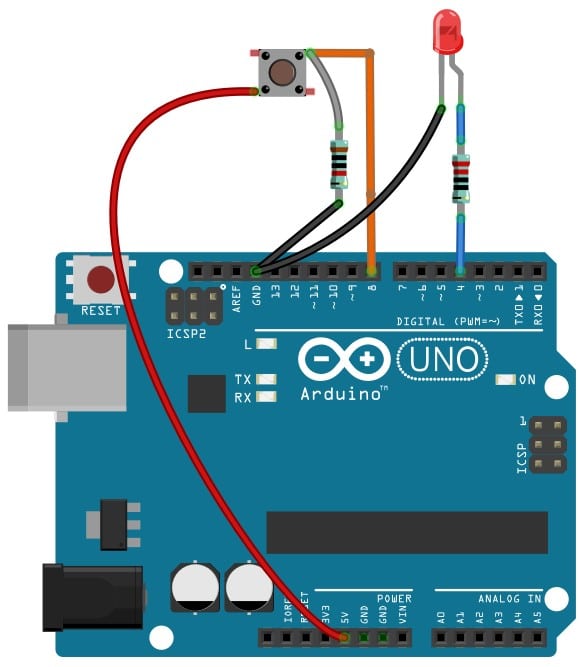
Here is the fundamental connection diagram you can build to complete the project with a switch in an active-low configuration.
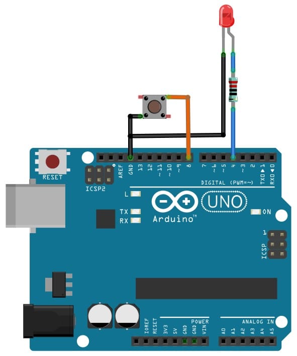
1) Connect an LED to Arduino Pin 4
I am using an LED to verify that our code is correct, and we can easily detect the push button’s status.
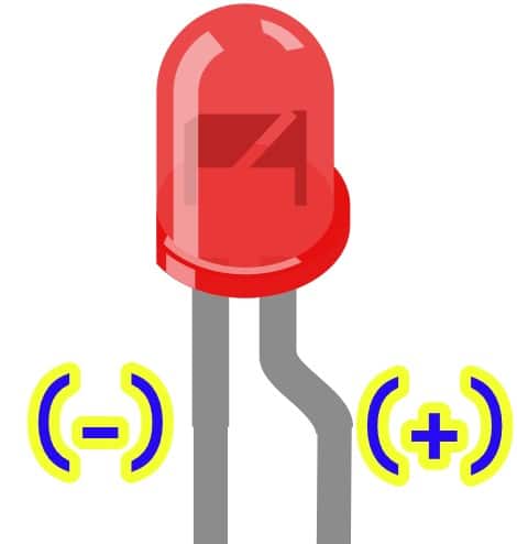
The flat side of an LED is the cathode (negative) and the bent pin of the LED indicates the Anode pin (positive).
Always use a small value of the resistor in series with the LED to protect components from brownout due to over current.
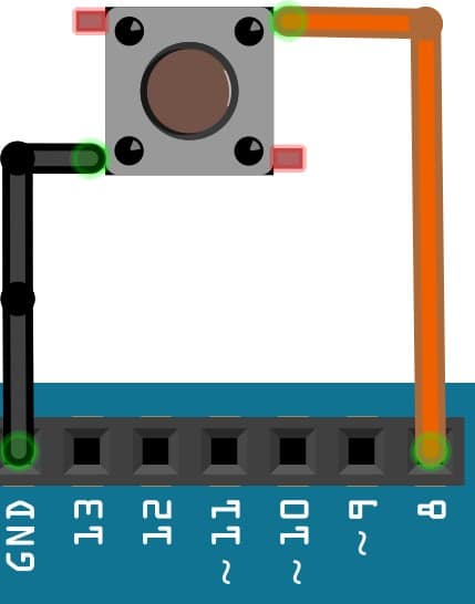
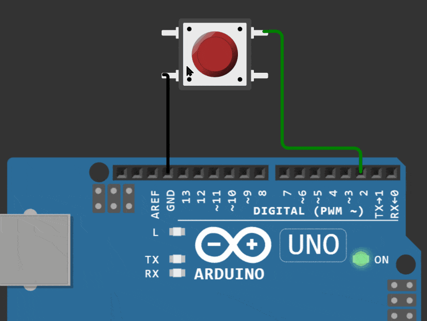
2) Connect the switch to the Arduino
Connect one pin of the Switch to the GND pin and the other pin to pin number #8.
Make sure that your connection looks as shown in the below image.
3) Program the Arduino with the Example Pushbutton Code below
#define LED_PIN 2
#define BUTTON_PIN 8

unsigned int button_status = 0;

void setup() {
  // initialize digital pin LED_BUILTIN as an output.
  pinMode(LED_PIN, OUTPUT);
  pinMode(BUTTON_PIN, INPUT_PULLUP);
}

void loop() {
  button_status = digitalRead(BUTTON_PIN);

  if (button_status == 0) {
    digitalWrite(LED_PIN, HIGH);
  } else {
    digitalWrite(LED_PIN, LOW);
  }
}
I will describe what each line of code does and its significance.
pinMode(BUTTON_PIN, INPUT_PULLUP);
BUTTON_PIN is a constant, and the value is 8. The pinMode function configures the #8 pin as input and enables the internal pull-up.
Internal pull-up ensures that the Arduino Pin will be tied to 5 V (Logic HIGH) internally via a resistor.
You use internal pullup or pulldown when you want the input pin to be at a defined stage (when the push button is released)
button_status = digitalRead(BUTTON_PIN);
digitalRead function returns either 1 or 0 which will be stored in the variable button_status.
You use button status to turn on the LED on or off. It helps to verify both the connections and the logic.
4) Arduino Simulation for the active-low pushbutton example
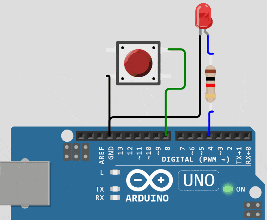
Congratulations! That completes the first example of connecting the push button to an Arduino. If you are having trouble, recheck the connections and the code.
If you are in doubt, feel free to drop a comment, I will be happy to help.
You will use internal pullup when the external signal is low when active. Examples of such pins are Active low Reset Signals, Chip select lines, etc.
You should terminate these lines with a pullup resistor (internal or external). Using an internal resistor for pullup saves space on the PCB and reduces the component count by 1.
Project 2: How To Connect Active-High Push Button To An Arduino
What is an active-high configuration?
Active high configuration is when you press the push button, you either short the input pin the 5 V directly or through a very low-value resistor.
Arduino will read the pin status as logic HIGH.
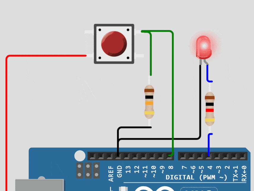
You can see the connection diagram to complete the project with a switch in an active-high configuration below.
You have to use a resistor (typically about 10 kOhms to 100 kOhms) to pull the input line to the ground when the switch is inactive.
1) Make the connections as shown in the image above
Follow the similar steps followed in the earlier project. Notice that you have to use a pull-down resistor of a specific value. You can use any value between 10 kOhms and 100 kOhms.
The switch is connected to the 5 V pin instead of the GND pin like in the earlier project.
2) Program the Arduino
You can reuse the Arduino code which you used in the earlier project. You can notice that the logic is now inverted.
When you press the button, the LED turns off and vice-versa.
Follow the similar steps followed in the earlier project. Notice that you have to use a pull-down resistor of a specific value. You can use any value between 10 kOhms and 100 kOhms.
3) Arduino Simulation for the active-high pushbutton example
You find the applications of pulldown configuration when a switch, when closed, provides a logic HIGH.
Arduino doesn’t have an internal pulldown option.
Project 3: How To Read The Status Of The Push Button Using Polling And Interrupt Methods
We already saw a couple of examples where we read the status of pushbuttons. We used a particular instruction, digitalRead, to read the status of the pin.
button_status = digitalRead(BUTTON_PIN);
You were repeatedly reading the status of the BUTTON_PIN in the loop() function. The polling method is simple to use.
There is a disadvantage to using the polling method. The polling mechanism will be less helpful to you when:
- You have to read the status of the button as soon as it changes
- You have to read the status of the button while you are in mid of another task
If there are ten other tasks, the poling method makes you wait for the ten tasks to complete before you can check the status of the button pin again. In specific scenarios, this will not be acceptable.
For example: when the button presses are for a short duration.
What is the interrupt method of reading the status of Pushbuttons?
I will show you a step-by-step procedure to configure Arduino to read the button’s status in the interrupt method. In this example, we will blink the onboard LED connected to pin #13 of the Arduino.
Pins #2 and #3 of Arduino UNO support external interrupts. You can connect push buttons with either of those pins.
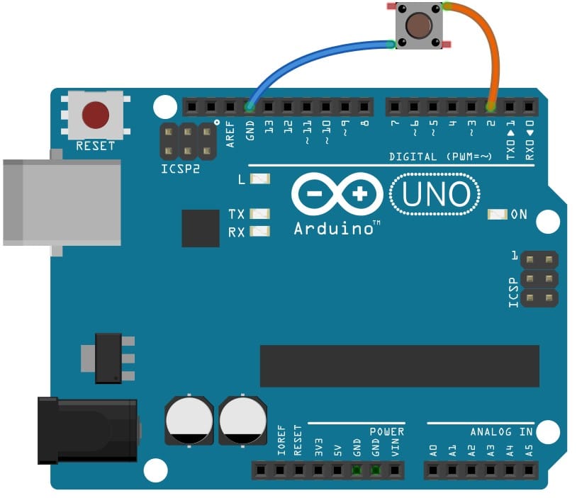
1) Start with a new sketch
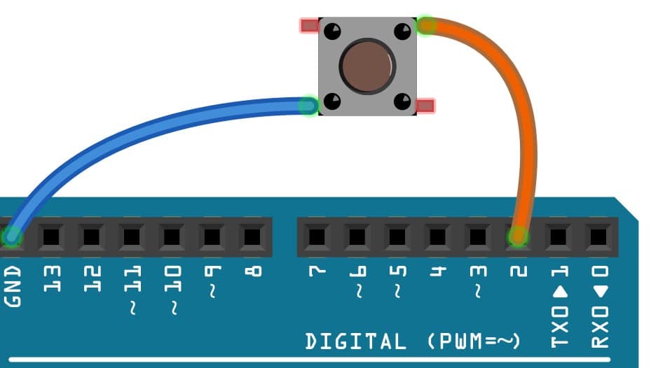
Connect the switch between Arduino Pin #2 and GND pin.
2) Copy the below code into a new sketch and program the Arduino
const byte ledPin = 13;
const byte interruptPin = 2;
volatile byte state = LOW;

void setup() {
  pinMode(ledPin, OUTPUT);
  pinMode(interruptPin, INPUT_PULLUP);
  attachInterrupt(digitalPinToInterrupt(interruptPin), blink, CHANGE);
}

void loop() {
  digitalWrite(ledPin, state);
}

void blink() {
  state = !state;
}
3) Pushbutton interrupt Code breakout and explanation
In the example, I define a function by name blink(). This function will be invoked whenever there is a change in the state of the push button.
We just toggle the value of the variable state between 1 and 0 every time the interrupt function is called.
void blink() {
  state = !state;
}
How do you tell to the Arduino to call the interrupt function? It is done in this particular line below.
attachInterrupt(digitalPinToInterrupt(interruptPin), blink, CHANGE);
The function attachInterrupt takes three arguments:
- The interrupt pin the association to be done with
- The function should be called when there is an event
- The type of event for which this function should be called
The event in our example is CHANGE. The function will be called whenever there is a change in the interrupt status from 1 to 0 and 0 to 1.
The options for the type of event are as below:
- LOW to trigger the interrupt whenever the pin is low,
- CHANGE to trigger the interrupt whenever the pin changes the value
- RISING to trigger when the pin goes from low to high,
- FALLING for when the pin goes from high to low.
4) A comparison between Interrupt mode and Polling Mode
In this table, I am listing the key differences between the two methods we discussed.
| INTERRUPT MODE | POLLING MODE |
| The event will be independent of the task the CPU is working on (asynchronous) | Synchronous to the CU tasks. Occurs at regular intervals |
| Very efficient to handle tasks which are less frequent | Less efficient |
| Suitable for battery-powered applications | Not suitable for battery applications as polling takes a lot of CPU cycles |
| Needs more code for one-time configuration | Simple to configure |
5) Pushbutton in Interrupt mode simulation
Notice that the state of the LED changes when you press the switch and again changes when you release the key.
The event type was defined as CHANGE; hence you see this behavior.
Project 4: What Is Debounce Problem And How To Avoid it In Arduino?
Every switch has a spring mechanism, due to which there will be a lot of make and break connections when you switch from one state to another state.
The below image shows you the bounce effect of the button in a simple way.
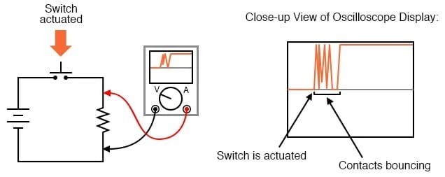
- When you close the switch, the actual circuit will close and open several times for a few ms before it closes completely.
- This unwanted behavior can trigger multiple interrupts in your project for a single press causing wrong counts.
- There are both hardware and software methods to prevent the issue.
- Software debouncing doesn’t need external hardware and is easy to implement
In this project, I will give you an example debounce library which solves the problem.
The library is called ezButton and is very easy to use.
1) Start with a new sketch
To use the ezButton library, you have to copy the two source files into the same directory in which you have stored the Arduino sketch.
- ezButton.h
- ezButton.cpp
OR
You can install the ezButton library. It will help you save a lot of time. Also, it ensures that you will be employing updated libraries all the time.
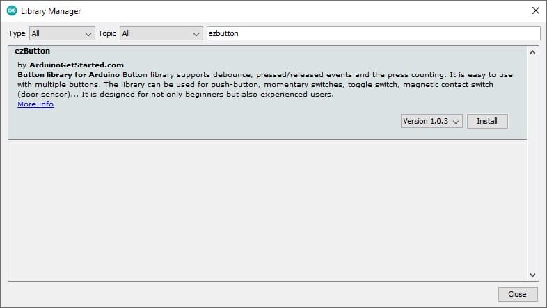
2) Install the ezButton library
Follow the steps below to easily install the ezButton library.
1. Click on Tools option
2. Select Manage Libraries
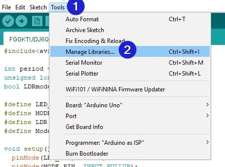
3. Search for ezButton library and click on install
3) Copy the below code into your Arduino sketch
/*
 * Created by ArduinoGetStarted.com
 *
 * This example code is in the public domain
 *
 * Tutorial page: https://arduinogetstarted.com/tutorials/arduino-button-library
 *
 * This example reads the state of a button with debounce and print it to Serial Monitor.
 */

#include"ezButton.h"

ezButton button(7);  // create ezButton object that attach to pin 7;

void setup() {
  Serial.begin(9600);
  button.setDebounceTime(50); // set debounce time to 50 milliseconds
}

void loop() {
  button.loop(); // MUST call the loop() function first

  if(button.isPressed())
    Serial.println("The button is pressed");

  if(button.isReleased())
    Serial.println("The button is released");
}
Once you run the code on an Arduino, you will see the messages on the terminal when the keypress/release event occurs.
You can see that the code is much more straightforward to use once you use the library. There are several other useful functions other than debouncing logic, such as:
- checking the state of the button
- Support multiple buttons
- Providing time events for button actions
- Programmable option for long-press and short press etc.
Conclusion
In this article, we saw how to connect a push button to an Arduino. I have shown the connections needed and the Arduino code you need to use. Push buttons are always handy.
I hope you can now confidently use push buttons in other projects. I have used the push buttons to control fan speed and light patterns in recent projects.
I would love to hear your feedback. Did you find this article beneficial? Do you have any feedback to make this article more helpful?
Please share your feedback in the comments section. I will be glad to respond to all your comments.
Feel free to share the projects you built using the pushbuttons. I will be excited to know more about it.
Now it is your turn to suggest a topic you would like to learn about next!
Don’t forget to share the article with your friends!

I am Puneeth. I love tinkering with open-source projects, Arduino, ESP32, Pi and more. I have worked with many different Arduino boards and currently I am exploring, Arduino powered LoRa, Power line communication and IoT.