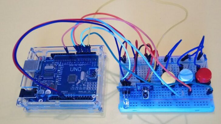
In this blog post, you will learn how to build a universal, programmable IR remote using Arduino. An infrared (IR) remote control is a common device used to control various electronic appliances such as TVs, air conditioners, and DVD players. With the help of Arduino, we can create our own IR remote that can be programmed to control multiple devices and unify multiple remote controls into one.
By the end of this tutorial, you will know how to use infrared receivers and transmitters, and how to store data in non-volatile EEPROM. You also will have the prototype for a programmable IR remote that you can modify or extend to your liking. It will allow you take your existing IR remotes for TV, Fan and so on, and copy the function of their keys on the IR remote, we are building here.
So, let’s get started and dive into the exciting world of Arduino and IR remote control!
Required Components
Makerguides.com is a participant in the Amazon Services LLC Associates Program, an affiliate advertising program designed to provide a means for sites to earn advertising fees by advertising and linking to products on Amazon.com. As an Amazon Associate we earn from qualifying purchases.
Below you will find the components required to build the programmable IR remote. You also will need an IR remote, if you don’t already have one.

Arduino Uno

Dupont Wire Set

Breadboard

USB Cable for Arduino UNO

Resistor & LED kit
IR Receiver Transmitter
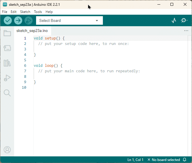
Arduino IDE
Connecting the Parts
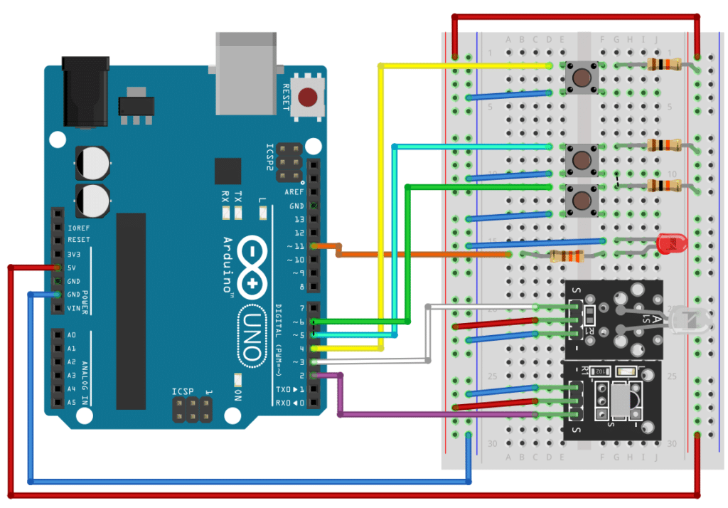
In this section I will show you how to connect the components to the Arduino. The picture below shows the complete wiring. We will start by connecting the power supply to the breadboard.
Power supply
Run a blue wire from the GND pin of the Arduino to the negative power rail of the breadboard (marked with a blue line). Then connect the 5V pin of the Arduino to the positive power rail (marked with a red line) with a red wire.
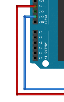
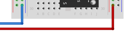
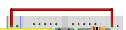
In addition, connect both positive power rails of the breadboard with another red wire. This ensures that we have positive power on both rails.
IR Receiver Module
Next, I will show you how to connect the IR receiver. It will receive the infrared signals emitted by an IR remote. It then sends those signals to the Arduino, where they are decoded.
Run a blue and red wire from the receiver to the corresponding power rails of the breadboard. The negative side is usually marked with (-) sign on the receiver, while the middle pin tends to be the positive pin. After that we connect the signal pin (S) of the receiver to pin 2 of the Arduino; below shown using a purple wire.
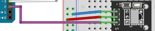
After the receiver is connected, let’s connect the transmitter module.
IR Transmitter Module
The IR transmitter is the module with the white/transparent IR LED. This module emits the infrared signals used to control devices.
Again, we first connect the power supply (red and blue wire). After that we connect the signal pin (S) on the transmitter to pin 3 on the Arduino using a white wire.
Since our IR remote will be programmable we need a status LED. It will tells us whether we are in programming mode or sending mode. Below is the description on how you wire up the status LED.
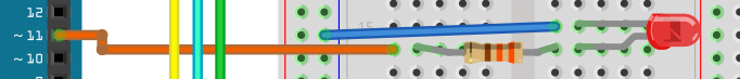
Status LED
Place a red LED on the breadboard and connect the cathode (that is the shorter pin) of the LED with a blue wire to the negative power rail of the breadboard. Then connect a 330 Ohm resistor to the anode of the LED (the longer pin). Finally, connect the resistor with an orange wire to pin 11 on the Arduino.
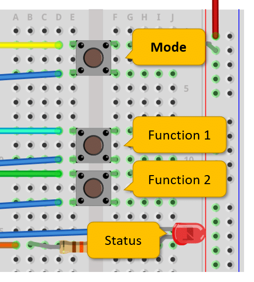
Buttons
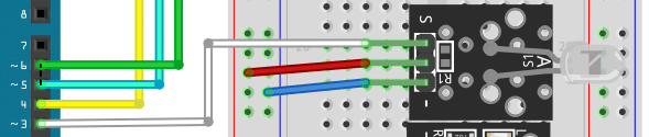
Lastly, we need three buttons. One button to switch between the programming mode and the normal mode of the IR remote. And two other buttons for two different functions of the remote. For instance, to increase volume and decrease volume.
As you can see below, all three buttons are connected in the same way. A 10K Ohm resistor serves as a pull-up resistor and is connected to the positive power rail. The pin on the other side of the button is connected to an input pin on the Arduino (more about that below). The other pin is connected with a blue wire to the negative power rail of the breadboard.
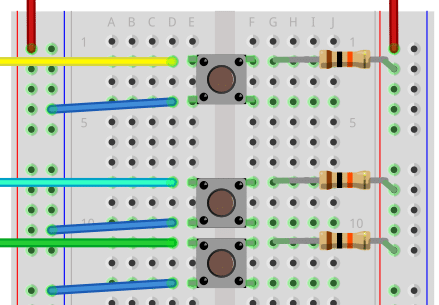
In the normal, open state of the push button, the input is connect to 5V via the resistor and we will read a HIGH signal. However, if you press a button, the input line connects to ground and we will read a LOW signal on the input.
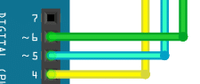
The top/first button will be our mode switching button. Connect it with a yellow wire to pin 4 on the Arduino. The button below will be for the first function. Connect it to pin 5 (cyan wire). And the last button is for the second function and we connect it with a green wire to pin 6.
That’s it. Everything is connected – hopefully correctly. In the next section we will have a look at the software.
Writing the Software
I firstly show you the entire code and then we will go through the individual parts to understand how it works. Just have a quick glance at it to get an overview.
#include "EEPROM.h"
#include "IRremote.hpp"
#include "TinyIRSender.hpp"

const uint8_t irReceivePin = 2;
const uint8_t irSendPin = 3;
const uint8_t modePin = 4;
const uint8_t func1Pin = 5;
const uint8_t func2Pin = 6;
const uint8_t ledPin = 10;
const uint8_t sRepeats = 2;

uint8_t modeReceive = HIGH;

struct Code {
  uint16_t adr;
  uint16_t cmd;
} code;

bool isOn(int btn) {
  return btn == LOW;
}

bool pressed(int pin) {
  return isOn(digitalRead(pin));
}

int memadr(int btnId) {
  return (btnId - 1) * sizeof(Code);
}

void store_code(int btnId, IRData &irData) {
  digitalWrite(ledPin, LOW);
  code = { irData.address, irData.command };
  EEPROM.put(memadr(btnId), code);
  delay(200);
  digitalWrite(ledPin, HIGH);
}

void send_code(int btnId) {
  digitalWrite(ledPin, HIGH);
  EEPROM.get(memadr(btnId), code);
  sendNECMinimal(irSendPin, code.adr, code.cmd, sRepeats);
  delay(200);
  digitalWrite(ledPin, LOW);
}

void toggle_mode() {
  modeReceive = modeReceive == LOW ? HIGH : LOW;
  digitalWrite(ledPin, isOn(modeReceive) ? HIGH : LOW);
  isOn(modeReceive) ? IrReceiver.start() : IrReceiver.stop();
  delay(200);
}

void send() {
  if (pressed(func1Pin)) {
    send_code(1);
  } else if (pressed(func2Pin)) {
    send_code(2);
  }
}

void receive() {
  if (IrReceiver.decode()) {
    IRData &irData = IrReceiver.decodedIRData;
    IrReceiver.printIRResultShort(&Serial);
    if (pressed(func1Pin)) {
      store_code(1, irData);
    } else if (pressed(func2Pin)) {
      store_code(2, irData);
    }
    IrReceiver.resume();
  }
}

void setup() {
  Serial.begin(9600);
  IrReceiver.begin(irReceivePin, ENABLE_LED_FEEDBACK);
  pinMode(ledPin, OUTPUT);
  pinMode(modePin, INPUT);
  pinMode(func1Pin, INPUT);
  pinMode(func2Pin, INPUT);
  digitalWrite(ledPin, LOW);
}

void loop() {
  if (pressed(modePin)) toggle_mode();
  isOn(modeReceive) ? receive() : send();
  delay(100);
}
Included libraries
For this project you will need to install the following libraries. EEPROM is used to store the programmed IR codes. The IRremote library is used to decode the IR signals we are receiving from an IR remote. And TinyIRSender is part of the IRremote lib and allows us to send IR signals – though limited to the NEC protocol.
#include "EEPROM.h"
#include "IRremote.hpp"
#include "TinyIRSender.hpp"
Constants
In the following code block we define which pins on the Arduino are used for which component. irReceivePin and irSendPin are the pins connected to the IR receiver and transmitter. modePin, func1Pin and func2Pin are connected to the buttons. The status LED is controlled via the ledPin. And sRepeats defines how often a IR command is repeated when sending.
const uint8_t irReceivePin = 2;
const uint8_t irSendPin = 3;
const uint8_t modePin = 4;
const uint8_t func1Pin = 5;
const uint8_t func2Pin = 6;
const uint8_t ledPin = 10;
const uint8_t sRepeats = 2;
Data structures
In addition to the constants, we need a variable to store the current mode (programming or normal) of our IR remote. modeReceive is HIGH, when we are in programming mode, and LOW otherwise.
uint8_t modeReceive = HIGH;

struct Code {
  uint16_t adr;
  uint16_t cmd;
} code;
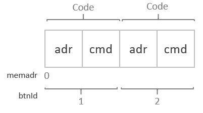
The Code struct stores the address (adr) and command (cmd) of the IR codes we are going to receive, store and send. For instance, my IR remote sends the address 0x20 and the command 0x17, when the VOL+ key is pressed.
For more details, see the documentation of the IRremote lib or have a look at our tutorial on How to use an IR receiver and remote with Arduino.
Helper functions
To keep the code as simple and readable as possible, we implement a few helper functions. The isOn() function returns True, if a button is LOW, which means it is pressed down. With the pressed() function we read the state of an input pin and then use isOn() to determine if the connected button is pressed.
bool isOn(int btn) {
  return btn == LOW;
}

bool pressed(int pin) {
  return isOn(digitalRead(pin));
}
Memory address function
To store the received IR codes in memory we need a function that tells us at which address to store the data. The memadr() function is used calculate at which memory address in the EEPROM we store and read IR command codes from.
int memadr(int btnId) {
  return (btnId - 1) * sizeof(Code);
}
This function takes a btnId, which is 1 or 2 (for function 1 or 2) and computes the memory address. Have a lock at the following picture to understand the relationship between btnId, size of a Code struct and the memory address better.
IR code functions
For the actual storing and sending of IR codes, we use two functions. The following store_code() function takes a button id (btnId) and a data block (irData) of received IR data.
In the first step, we switch the status led off, to indicate that we are storing data.
void store_code(int btnId, IRData &irData) {
  digitalWrite(ledPin, LOW);
  code = { irData.address, irData.command };
  EEPROM.put(memadr(btnId), code);
  delay(200);
  digitalWrite(ledPin, HIGH);
}
Then we extract the code address and command from the data block and store it in a Code struct. We write this code struct to the EEPROM with put(), using the memadr() function to calculate the memory address.
We need to store the data in EEPROM because otherwise every time power is switched off the Arduino looses all the stored data. With the data in EEPROM the programmed commands/key remain stored, even when the Arduino is switched off.
After storing the data we wait for 200ms. This is to avoid unnecessary, repeated storage when the programming key remains pressed. And finally, we switch the status led back, to indicate the the programming is complete.
Sending of codes essentially works in reverse. Have a look at the send_code() function below. First we set the status led to HIGH, to indicate that we are sending. Then we get the code to send from the EEPROM for the pressed button (btnId). The sendNECMinimal() function, sends the code address and command with the given number of repeats (sRepeats).
void send_code(int btnId) {
  digitalWrite(ledPin, HIGH);
  EEPROM.get(memadr(btnId), code);
  sendNECMinimal(irSendPin, code.adr, code.cmd, sRepeats);
  delay(200);
  digitalWrite(ledPin, LOW);
}
After that we again wait for 200ms and switch the status led off to indicate the sending is complete.
Main functions
Now we have all the basic functions to build the main functions. We start with a toggle_mode() function that switches our remote from programming/receiving mode to sending mode and back. The first line does the toggling of the mode. In the second line, we switch the status led on, if we are in programming mode. If we are in normal mode the status led will be off.
void toggle_mode() {
  modeReceive = modeReceive == LOW ? HIGH : LOW;
  digitalWrite(ledPin, isOn(modeReceive) ? HIGH : LOW);
  isOn(modeReceive) ? IrReceiver.start() : IrReceiver.stop();
  delay(200);
}
In the third line, we switch the IrReceiver on or off depending on the mode. If we are in receiving mode, the IrReceiver will be started otherwise stopped. Finally, we have our usual delay of 200ms to deal we long button presses.
The send() function below uses send_code() to the send the IR codes stored for button 1 and 2. In other words, depending on which button is pressed, it will send the corresponding code.
void send() {
  if (pressed(func1Pin)) {
    send_code(1);
  } else if (pressed(func2Pin)) {
    send_code(2);
  }
}
Finally, the last of the main functions is receive(). There we receive the data transmitted from an IR remote and store it for button 1 or 2, depending on which button is currently pressed. For more detail on how to receive IR data have a look at our tutorial: How to use an IR receiver and remote with Arduino.
void receive() {
  if (IrReceiver.decode()) {
    IRData &irData = IrReceiver.decodedIRData;
    IrReceiver.printIRResultShort(&Serial);
    if (pressed(func1Pin)) {
      store_code(1, irData);
    } else if (pressed(func2Pin)) {
      store_code(2, irData);
    }
    IrReceiver.resume();
  }
}
Setup function
We are almost done! Only two more very simple functions are left to implement. In the setup() function, we establish serial communication, initialize the IrReceiver and set the IO modes for the pins. We also ensure that the status LED is switched off, which indicates that we are in sending mode at the start.
void setup() {
  Serial.begin(9600);
  IrReceiver.begin(irReceivePin, ENABLE_LED_FEEDBACK);
  pinMode(ledPin, OUTPUT);
  pinMode(modePin, INPUT);
  pinMode(func1Pin, INPUT);
  pinMode(func2Pin, INPUT);
  digitalWrite(ledPin, LOW);
}
Loop function
After all the hard work above, the main loop is now very simple. We watch the mode button connect to the modePin and if it is pressed we toggle the mode. Next we check if we are in receiving mode via isOn(modeReceive). If that is the case, we receive and potentially store IR data. Otherwise we send data.
void loop() {
  if (pressed(modePin)) toggle_mode();
  isOn(modeReceive) ? receive() : send();
  delay(100);
}
And that’s it! In the next section, I’ll quickly explain how to actually use the remote we just built.
How to Use the Remote
In this section, I will tell you how to actually use the remote. We have three button. The Mode button is used to switch from programming or receiving mode to sending mode. At the start the remote is in sending mode and the status led is off. If you shortly press the Mode button, the remote switches into the programming mode and the status LED will be on.
Programming
To program one of the two function keys you must point your other IR remote toward the receiver diode and press two keys together. The key on the other remote you want to store and the function key on our universal remote. The following picture, shows how we would store the Next Track key as Function 1.
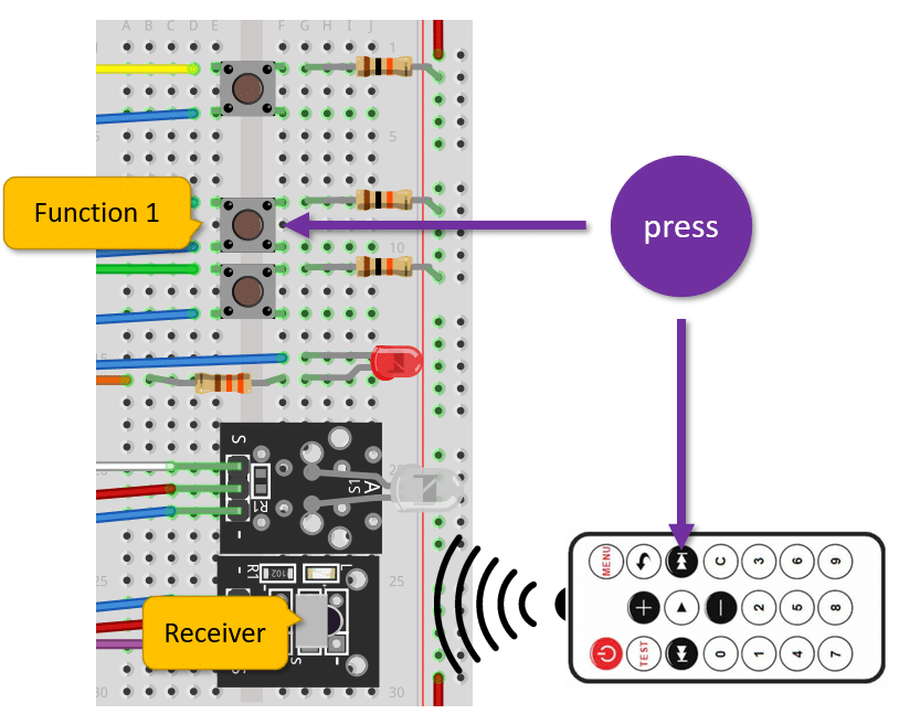
The status LED will shortly flicker to indicate that a function has been stored and you can then release the buttons.
Sending
To send IR commands, simply press the Mode button (the status LED should be switch to off) and press one of the function keys you have programmed. Again the status LED will flicker to indicate the command has been sent.
Debugging
Some IR remotes are not supported and you will not be able to program them. You can verify this by connecting the Serial monitor, switch to the programming mode (status LED should be on) and check if the IRremote library can decode the signal. The output should look similar to this:
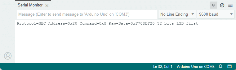
Here we successfully received a command with address 0x20 and command code 0x8.
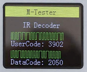
For debugging the sending functionality, one of these component testers will come in very handy. Otherwise, you have to rely on trial & error to find out what is wrong.
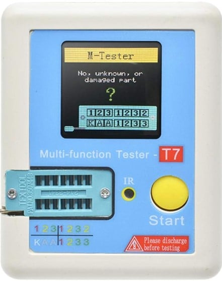
Multi-Function Tester
The component tester above can decode IR signals and a successfully received signal looks like this:
Conclusions
In this tutorial, you have learned how to build a universal, programmable IR remote using Arduino. By following the step-by-step instructions, you can easily create your own remote control that can operate a wide range of infrared devices.
We started by discussing the required parts for this project, which include an Arduino board, an IR receiver module, and an IR transmitter module. We described the wiring between these components and provided the code to control them. In addition, we explained how to use the remote to program IR commands from other remotes.
In conclusion, building an universal, programmable IR remote control with Arduino is a fun and practical project that can simplify your home entertainment experience.
If you have any further questions or need additional guidance, please refer to the Frequently Asked Questions section or explore the links provided for more resources and inspiration.
Happy building!
Frequently Asked Questions
Here are some commonly asked questions about building an universal, programmable IR remote with Arduino:
Can I have more function buttons?
Yes, just replicate the wiring of the existing buttons for the new buttons and extend the code. Specifically, the functions receive() and send() need to be extended to handle the additional buttons.
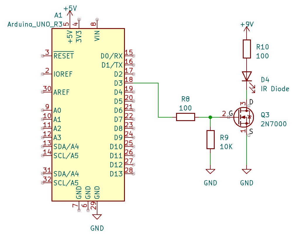
How can I increase the range of the IR remote?
You can connect additional IR LEDs to other output pins. Or you run an IR LED at a higher volage but this will require a transistor or MOSFET to control the signal input to the LED. Here is an example circuit that uses a 9V battery to drive an IR Transmitter Diode:
For more details and examples regarding MOSFETs have a look at our tutorial on Control Air-Conditioner via IR with ESP32 or ESP8266 and How To Control Fan using Arduino UNO.
It does not work with my IR remote?
The IrRemote library is great but does not support every and all IR communication protocol that exists. Specifically, for sending, we used TinyIRSender, which is limited to the NEC protocol but the IrRemote library supports other protocols as well. If that is not enough have a look at the IRremoteESP8266 as a possible alternative.
I want to control my air-con with the IR remote?
Try the IRremoteESP8266 library. It has great support for many air-conditioning units.
Can I use any Arduino board for this project?
Yes, you can use any Arduino board for this project as long as you can connect an infrared (IR) receiver and transmitter, and the required libraries are supported. An ESP32, for instance, would be a great alternative to an Arduino.
How do I know which IR codes to use for my devices?
You can find the IR codes for your devices by searching online or referring to the device’s user manual. Many manufacturers provide IR code databases that can be used with Arduino libraries. Alternatively, you can use an IR receiver module to capture the codes from an existing remote control. See our tutorial on How to use an IR receiver and remote with Arduino.
Can I control multiple devices with this IR remote?
Yes, you can control multiple devices with this IR remote. By programming different IR codes for each device, you can switch between them using buttons or a menu system in your Arduino code. Note, however, that the code above only supports the NEC protocol but luckily most IR remotes use it.
Can I add additional features to the IR remote?
Absolutely! The Arduino platform allows for endless customization. You can add features like a backlit LCD display, a rotary encoder for menu navigation, or even integrate it with other smart home devices using wireless communication protocols like Wi-Fi or Bluetooth.
If you have any more questions or need further assistance, feel free to ask in the comments section below.
Links
Below some useful links for additional explanations and alternative builds.
- IR Remote and Receiver with Arduino Tutorial (4 Examples)
- ESP32 And IR Remote Interface – A Complete Tutorial
- How to Control a Servo with an IR Remote
- Universal Arduino Remote : 10 Steps (with Pictures)
- Arduino Infrared (IR) Control… The Universal Remote …
- Arduino based universal TV Remote
- Arduino IR Remote Controller Tutorial – Setup and Map …
- Arduino Infrared Remote Tutorial : 7 Steps
Stefan is a professional software developer and researcher. He has worked in robotics, bioinformatics, image/audio processing and education at Siemens, IBM and Google. He specializes in AI and machine learning and has a keen interest in DIY projects involving Arduino and 3D printing.
Pierre
Friday 12th of January 2024
I am working with this code since 2 days and the EEPROM function don't work. I loose all the codes for my button. Is someting change in the library or other thing you know. Thank you, i really appreciate this project.
Stefan Maetschke
Friday 12th of January 2024
Hi, what Arduino board are you using? And can you test writing and reading from the EEPROM separately? For instance, is the example in the Arduino documentation working for you? https://docs.arduino.cc/learn/built-in-libraries/eeprom