
In this tutorial you will learn how to run an ESP32 lite on batteries with deep-sleep mode to control Halloween lights. And to make it really cool, we will use this to give a Halloween skull a pair of glowing red, scary eyes 😉
As part of this project you will learn about the Lolin32 lite development board, deep-sleep to preserve battery power, and how to create some simple lighting effects with LEDs.
Let’s have some fun.
Required Parts
Makerguides.com is a participant in the Amazon Services LLC Associates Program, an affiliate advertising program designed to provide a means for sites to earn advertising fees by advertising and linking to products on Amazon.com. As an Amazon Associate we earn from qualifying purchases.
Below you will find the components required to build the project. For this project I am using an older ESP32 board, which has been deprecated but you can still get it for a very low price. That’s the one listed below. There is a successor model with improved specs, which you can find here. I haven’t tried this one myself but it should work just the same.
Also the skull I used is different from the one I listed below. I think the one below actually looks better but it is a bit smaller. However, I tried and the board and the battery fit in very nicely.
Finally, all the 903052 LiPo batteries I could find have the wrong connector. So the ones suggested below! You will need to cut off the connector and replace it by an 2.0mm JST PH 2-pin connector. But I like the form factor of these batteries since they have almost the same dimensions as the ESP32 board.
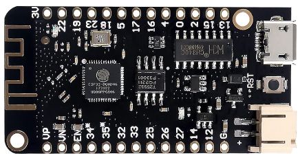
ESP32 lite

Dupont Wire Set

Breadboard
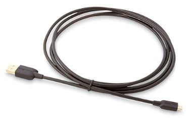
USB Data Cable

Resistor & LED kit
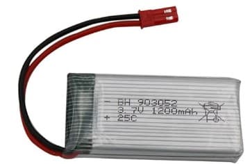
1200mAh Battery

Skull
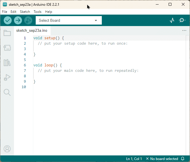
Arduino IDE
Connecting the Parts
We want to build a Halloween skull with a pair of red glowing eyes. For the eyes we use two red LEDs. Furthermore, we want those eyes to blink or show some other effect. Which means we will need a microcontroller.
The picture below shows you how to connect those parts.
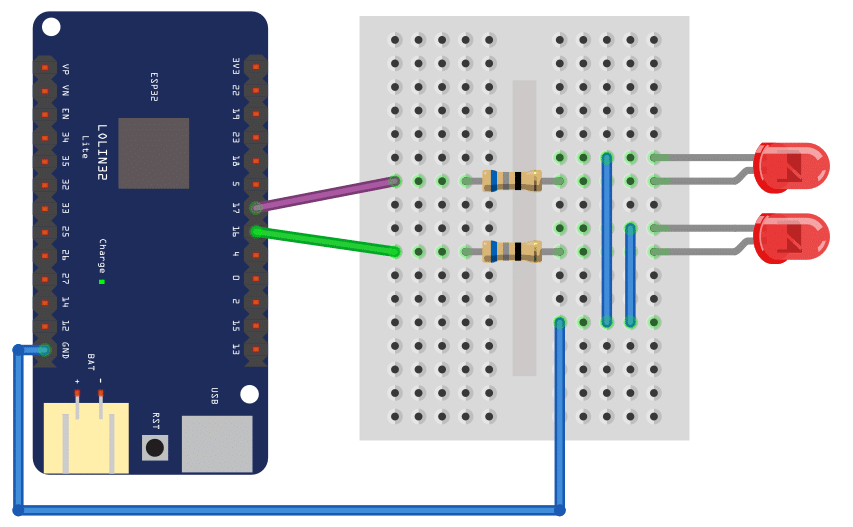
As you can see, it is very simple. We connect the GND pin of the ESP32 board with a blue wire to the Cathodes of the two LEDS (those are the shorter pins.) The Anodes (the longer pins) of the LEDs are connected to pin 16 and 17 via a 68Ω resistor (purple and green wire).
It doesn’t matter much, which LED you connect to witch pin on the board. Just make sure that you know, which LED will be the right eye and which the left eye.
For the time, we use the USB port for programming and power supply. So no battery needs to be connected.
Writing the Software
In this section, I will show you how to implement the control software for the LEDs. We are aiming for the following effect:
- a 5 second phase where the eyes/LEDs slowly grow darker with some random flicker at the end
- followed by another 5 second phase, where the LEDs are completely switched off.
We want to give the impression that the skull suddenly wakes up, stares at you with red, glowing eyes and then slowly dozes off until it sleeps for a while.
If you are completely new to the Arduino world, maybe have a look at our tutorial How To Blink An LED Using Arduino first. Otherwise, just have a quick glance at the code below. I will explain the details in the following sections.
const int ledPin1 = 16;
const int ledPin2 = 17;

const int ts_ms = 10;
const int dozingoff_ms = 5000;
const uint64_t sleeping_ms = 5000;

void set_brightness(int brightness) {
  analogWrite(ledPin1, brightness);
  analogWrite(ledPin2, brightness);
}

int effect(int t) {
  long flutter = random(0, 30);
  int brightness = 255 * (dozingoff_ms - t) / dozingoff_ms;
  return brightness < 150 ? brightness + flutter : brightness;
}

void dozingoff() {
  for (int t = 0; t < dozingoff_ms / ts_ms; t++) {
    delay(ts_ms);
    int brightness = effect(t * ts_ms);
    set_brightness(brightness);
  }
}

void sleeping() {
  esp_sleep_enable_timer_wakeup(sleeping_ms * 1000);
  esp_deep_sleep_start();
}

void setup() {
  pinMode(ledPin1, OUTPUT);
  pinMode(ledPin2, OUTPUT);
}

void loop() {
  dozingoff();
  sleeping();
}
Constants
We start by defining some constants. ledPin1 and ledPin2 are obviously the pins where the LEDs are connected.
const int ledPin1 = 16;
const int ledPin2 = 17;

const int ts_ms = 10;
const int dozingoff_ms = 5000;
const uint64_t sleeping_ms = 5000;
After that, we have some timing constants. We use those to regulate how long the dozing-off and the sleeping phases are. Those times are in milliseconds (ms), so 5000ms is 5 seconds.
You can change these constants pretty much anyway you like to make the two phases shorter or longer. Make dozingoff_ms larger if you want a slower dozing off. And make sleeping_ms larger if you want a longer sleeping phase.
We will talk about the time step ts_ms later.
Helper functions
Next we implement some useful helper functions to keep the code nicely structured and readable. We use the set_brightness() function to sets the brightness of the two LEDs. Where analogWrite() is doing the actual work.
void set_brightness(int brightness) {
  analogWrite(ledPin1, brightness);
  analogWrite(ledPin2, brightness);
}
Note that we will need a pin that supports Pulse Wide Modulation (PWM) for analogWrite() to work. For the ESP32 board we are using here that is not a problem. Pins 16 and 17 are PWM pins and so are almost all pins on that board. Have a look at the pinout diagram under Pinout of the ESP32 board.
The parameter brightness will be a value between 0 and 255, where 255 means maximal brightness.
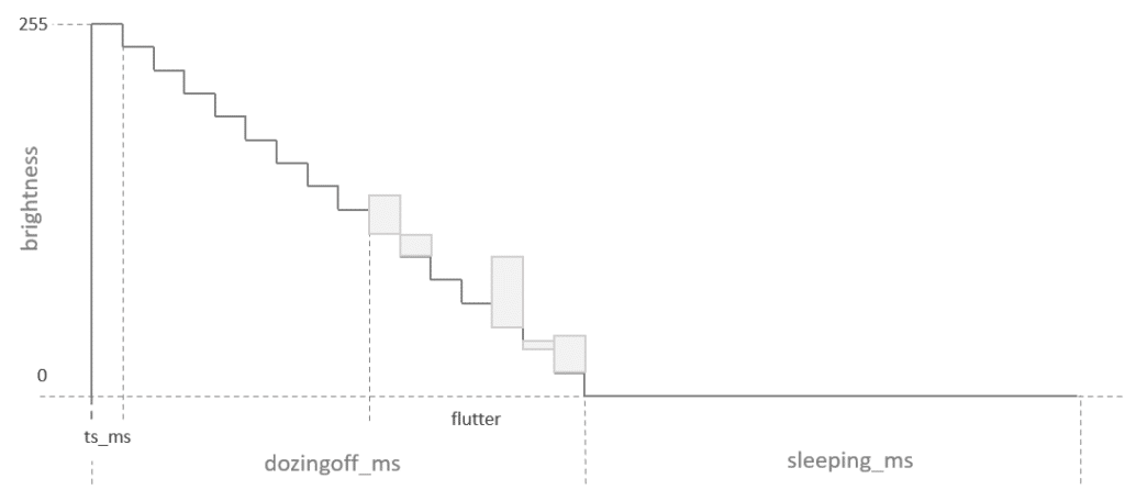
To create the dozing-off effect, we implement a function named effect(). Surprise, surprise. It takes a time step t as parameter and over time decreases the LED brightness from 255 to 0. To make it more interesting, we add a random flickering about halfway in the dozing off. This will give the impression of the skull fighting against the sleep with fluttering eye lids. I know, skulls have no eye lids, nevertheless …
int effect(int t) {
  long flutter = random(0, 30);
  int brightness = 255 * (dozingoff_ms - t) / dozingoff_ms;
  return brightness < 150 ? brightness + flutter : brightness;
}
I hope the following diagram will make it clear how this works in detail.
Dozing-off function
We are going to use the effect() function in the dozingoff() function shown below. This function simply iterates over the time steps of length ts_ms, calculates the brightness via the effect() function and then sets the brightness of the LED accordingly.
void dozingoff() {
  for (int t = 0; t < dozingoff_ms / ts_ms; t++) {
    delay(ts_ms);
    int brightness = effect(t * ts_ms);
    set_brightness(brightness);
  }
}
You can change the length of the time steps which will result in a smoother or coarser effect. I picked 10ms, which works nicely. You can save battery power by making it longer but the animation will not be as smooth.
Sleeping function
To make the head sleep, we could simply set the brightness of the LEDs to zero and then wait for the duration of the sleeping phase. The code below does exactly that.
void sleeping() {
  set_brightness(0);
  delay(sleeping_ms);
}
However, we would waste valuable battery power, since the microprocessor is still running without actually doing anything during the sleeping phase. Instead, we put the microprocessor in actual deep-sleep mode, where it consumes much less power. The code below shows you how that is done.
void sleeping() {
  esp_sleep_enable_timer_wakeup(sleeping_ms * 1000);
  esp_deep_sleep_start();
}
First, we specify how we want to wake up. There are different ways to do that but here we set a timer via esp_sleep_enable_timer_wakeup(). It takes the sleeping time in micro-seconds. That’s why we need to multiply sleeping_ms by 1000.
And in the second line we simply start the deep sleep mode by calling esp_deep_sleep_start(). Note that this means the setup and the loop function will run, then the board falls asleep, wakes up and the repeats the cycle, starting by calling the setup function.
Setup function
Our setup is very simple. We just switch the pins that control the LEDs into output mode. Done.
void setup() {
  pinMode(ledPin1, OUTPUT);
  pinMode(ledPin2, OUTPUT);
}
Loop function
And thanks to our helper functions, the loop function is also beautifully simple. We doze-off, then sleep and that’s it.
void loop() {
  dozingoff();
  sleeping();
}
However, note the loop function will run only once, since we enter deep-sleep mode when sleeping and then restarting the board when waking up.
Power savings
We want to run our scary skull on batteries. And the obvious question to ask is, for how long will it run and how much does the deep-sleep mode help.
I am using a 1200mAh LiPO battery. And I measured the current during the dozing-off phase (LEDs on) as 50mA. In deep-sleep the board consumes only 0.054mA and if I use delay() instead, the consumption goes up to 39mA. Now, let’s do the math.
First, we convert the battery capacity to Coulomb:
1200mA x 3600s = 4320000mC
For the dozing-off phase, when the board is awake for 5 seconds, we consume
50mA x 5s = 250mC
During the 5 seconds in deep sleep mode, however, we consume only
0.054mA x 5s = 0.27mC
In total, we consume 250mC + 0.27mC = 250.27mC every 10 seconds.
Therefore, we get a continuous running time of about
10s * 4320000mC / 250.27mC ≈ 17263s ≈ 48 hours = 2 days
If we don’t use the deep-sleep mode that time is cut in half. If you want to increase the running time make the sleeping phase longer (or the dozing-off phase shorter). Or use a bigger battery , of course.
Pinout of the ESP32 board
In this section, I want to highlight some specific aspects of the Lolin32 lite board we are using for this project. You will find the pinout below.
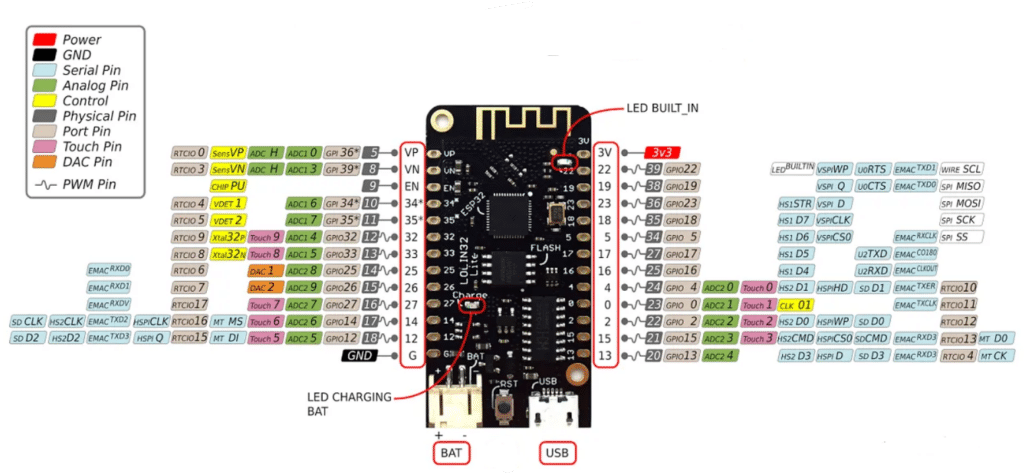
This board is especially suited for battery power project, since it has a battery connector and a charging circuit with 500mA maximum charging current. This means you can connect a LiPo battery to the board, run the board on battery power and charge via the USB port. Very nice!
Furthermore, the deep sleep currents are pretty low. The spec says 125mA with WiFi on and 45mA with WiFi off, which is what I roughly measured as well.
Without a battery connected, and the board powered over USB, you will see a continuous flickering of the charging LED. This is normal! If you connect a battery the flickering will stop. If the battery is charging the LED will be solid blue and will switch off when fully charged.
Note that the board operates with a 3.3V logic level. So not all modules that you get for an Arduino will necessarily work with this board, since the Arduino runs on 5V.
Finally a word of warning. The battery connector is a 2.0mm JST PH 2-pin connector. But most batteries with this connector will have a reverse polarity! Look carefully at the markings of the board. In the picture above the plus pin is on the left side. Make sure the red wire from the battery will connect to the plus pin. I had to cut off and reverse the connector on my battery.
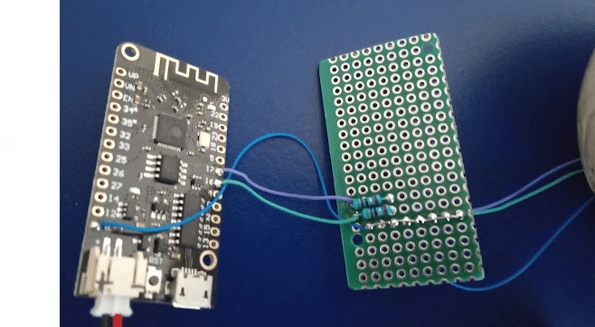
Wiring of the Halloween Skull
While the breadboard is great for testing out the circuit, it will not fit into the skull. Once you confirmed everything is working you will need to solder the wires to the board and the LEDs. Here is how my wiring looks like
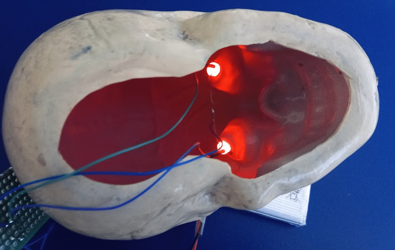
The skull I bought had no removable top. So I had to cut out the bottom and drill two holes for the eyes. I also repainted it and added some weathering. But I am very happy with the end product
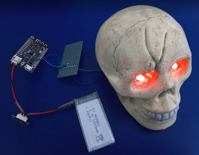
Especially after everything is nicely tucked away:

Conclusion
In this article, we have explored how to control Halloween lights using an Lolin32 lite on battery power. We started by listing the required parts, including the LoLin32 Lite board, which is a great choice for battery powered project. We then discussed the process of connecting the parts and wiring the LEDs for the Halloween skull.
Next, we wrote the software for the ESP32, which involved programming it to control the lights and enter deep sleep mode to conserve battery power. This allows the lights to be operational for an extended period without the need for constant power supply.
Overall, this project provides a fun and creative way to add a spooky touch to your Halloween decorations. By using the ESP32 and a few simple components, you can easily control your Halloween lights and create a memorable experience for trick-or-treaters.
Of course, we could do a lot more. Adding a PIR motion sensor or radar sensor to switch on the lights only when a person is detected. Or adding a sound module and more lighting effects, or controlling the head via Wi-Fi. There are endless possibilities.
If you have any questions or encounter any issues while working on this project, please refer to the Frequently Asked Questions section below for further guidance.
Frequently Asked Questions
Here are some commonly asked questions about controlling LEDs using ESP32 on battery:
Q: Can I use any ESP32 board for this project?
A: Yes, you can use any ESP32 board for this project. However, in this blog post, we specifically use the LoLin32 Lite board, since it is easy to run on battery.
Q: How long will the battery last?
A: The battery life will depend on various factors, such as the capacity of the battery, the power consumption of the lights, and the sleep duration of the ESP32. It is recommended to use a high-capacity battery and optimize the code to minimize power consumption for longer battery life. See the calculations above.
For more advance ways to save power have a look at this excellent post: ESP32: Tips to increase battery life.
Q: Can I use different lights instead of the Halloween skull?
A: Absolutely! You can use any type of lights you prefer. The wiring and code may vary depending on the lights you choose, but the overall concept remains the same. A nice idea would be to use RGB LEDs to have some color effects.
Q: Is it possible to control multiple sets of lights with one ESP32?
A: Yes, it is possible to control more lights with one ESP32. You can connect multiple lights in parallel or use a multiplexer to control them individually. However, keep in mind that the power consumption will increase accordingly, affecting the battery life.
Q: Can I modify the code to add more features?
A: Definitely! The code provided in this blog post is a basic example to get you started. You can modify and expand it to add more features, such as different lighting patterns, remote control, or integrating with other smart home devices.
Q: Can I power the ESP32 using a USB cable instead of a battery?
A: Yes, you can power the ESP32 using a USB cable instead of a battery. However, the purpose of this project is to make it portable and wireless by using a battery. If you prefer a wired setup, you can connect the ESP32 to a power source via USB.
Links
Some useful links with additional information are listed below.
- Lolin32 classic vs Lolin32 lite
- ESP32: Tips to increase battery life
- Deep Sleep — Arduino-ESP32 2.0.6 documentation
- ESP32 External Wake Up from Deep Sleep
- In-Depth: ESP32 Deep Sleep & Wakeup Sources
- ESP32 WeMos LOLIN32 Lite high resolution pinout and specs
- ESP32 Power Consumption Comparison
Stefan is a professional software developer and researcher. He has worked in robotics, bioinformatics, image/audio processing and education at Siemens, IBM and Google. He specializes in AI and machine learning and has a keen interest in DIY projects involving Arduino and 3D printing.