
In this tutorial, we will learn how to build a motion-activated, battery-powered, night light using an ESP32 lite and a PIR (Passive Infrared) sensor. This project is perfect for adding a touch of automation to your home or workspace, providing a convenient and energy-efficient lighting solution.
By using a PIR sensor, our night light will only turn on when it detects motion in its vicinity, ensuring that it remains off when not needed. This feature not only saves battery life but also adds a layer of security by alerting you to any movement in the area. In addition we will exploit the deep-sleep mode of the ESP32 to further save energy.
To ensure that the night light only is active during night, we also will add a photoresistor or LDR to detect ambient lighting conditions.
In this tutorial, we will build two night lights; a very simple one, and a slightly more advanced one. The latter one will be integrated into a skull, making it a great gift or demonstration object.
To build this project, we will need a few essential components, which we will discuss in the next section. Don’t worry if you’re new to Arduino or electronics – this tutorial is beginner-friendly, and we will guide you through each step of the process.
So let’s get started!
Required Parts
Below you will find the components required to build the project. For this project, I am using an older ESP32 board, which has been deprecated but you can still get it for a very low price. That’s the one listed below. There is a successor model with improved specs, which you can find here.
Finally, all the 903052 LiPo batteries I could find have the wrong connector. You will need to cut off the connector and replace it by an 2.0mm JST PH 2-pin connector. But I like the form factor of these batteries since they have almost the same dimensions as the ESP32 board.
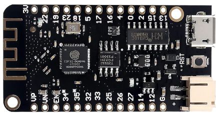
ESP32 lite
USB Data Cable

Dupont Wire Set

Breadboard

Resistor & LED kit
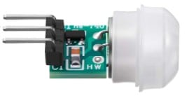
Motion Sensor
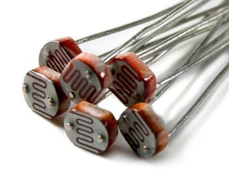
Photoresistor set
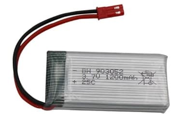
1200mAh Battery

Skull
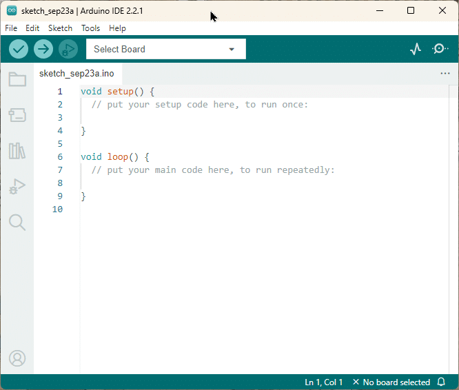
Arduino IDE
Makerguides.com is a participant in the Amazon Services LLC Associates Program, an affiliate advertising program designed to provide a means for sites to earn advertising fees by advertising and linking to products on Amazon.com. As an Amazon Associate we earn from qualifying purchases.
Light and PIR Sensors
In order to build a motion-activated night light, we first need to understand the two key components: the light sensor and the PIR (Passive Infrared) motion sensor.
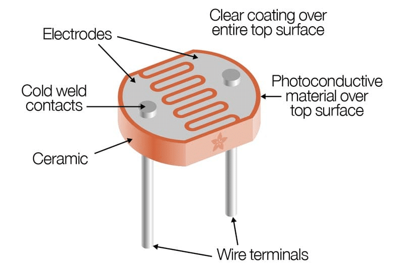
Light Sensor
A light sensor, also known as a photoresistor or LDR (Light Dependent Resistor), detects the ambient light level in the surroundings. It works by changing its resistance based on the intensity of light falling on it. When exposed to bright light, the resistance decreases, and when in darkness, the resistance increases.
For our night light, the light sensor will determine whether the light should turn on or off based on the surrounding light conditions. When the ambient light level drops below a certain threshold, indicating darkness, the light sensor will enable the output of PIR sensor and permit activating the night light.
PIR Sensor
The PIR sensor is a motion detection sensor that detects changes in infrared radiation emitted by objects in its field of view. It consists of a pyroelectric sensor that generates a voltage when exposed to infrared radiation. The PIR sensor is commonly used in security systems, automatic lighting, and other applications that require motion detection.
You will find that there are three common PIR motion detection modules. The large HC-SR501, the mid-size HC-SR505 and the small AM312 that we are using here. All of them would work but since we want to integrate the night light in a skull, we go with the smallest one. The AM312 also seems to have the lowest power consumption (8uA), though I did not measure that myself.
For more details on the HC-SR501 sensor or motion sensors in general see our tutorial HC-SR501 PIR Motion Sensor Arduino Tutorial (3 Examples).
When the PIR sensor detects movement within its range, it sends a signal to the microcontroller, indicating that motion has been detected. In our night light project, the PIR sensor will be used to trigger the light to turn on when motion is detected and turn off after a set period.
In the next section, we will discuss the base circuit we are going to use to detect motion at night.
Schematics of the Base Circuit
The simplest solutions to detect motion at night would be to connect the motion sensor (PIR) to one input pin of the ESP32 and the light sensor (LDR) to another pin. If we then detect a HIGH signal from the PIR sensor we could check the light level by reading the LDR sensor and then switch the light on or off.
This would work fine but has the disadvantage that we have to awake the ESP32 from deep-sleep every time motion is detected (regardless of ambient light). We would waste battery power, since there is no point reacting to motion if it is dark, since we want to have a night light.
One solution is to only send the high signal from the motion sensor to the ESP32 if it is dark. We can achieve this by using the following circuit.
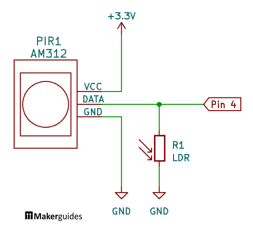
The PIR sensor sends its signal from the DATA pin to pin 4 of the ESP32. But we add the LDR as a pull-down resistor that will pull down the signal from the motion sensor to LOW when it is bright. Since the resistance of the LDR is very high when it is dark the PIR signal gets through. But when it is dark the LDR resistance is low and DATA output is essentially diverted to ground GND and pin 4 on the ESP32 will read a LOW signal.
If you need more details on how to detect light using an LDR have a look at our tutorial How to detect light using an Arduino.
In the following section I will show you how to use this circuit to build a simple night light.
Building a Simple Night Light
In this section we build a simple night light that switches on an LED if motion is detected in the dark.
Circuit for a Simple Night Light
Below you will find the circuit for this night light. It consists of the AM312 motion sensor (PIR), the photoresistor (LDR) to measure ambient light, and an LED with a current limiting resistor.
We connect the power supply for the motion sensor and its output to Pin 4 of the ESP32. After that we connect the LDR to the output of the PIR and to ground. Lastly, we add the LED, which is controlled via Pin 16 of the ESP32.
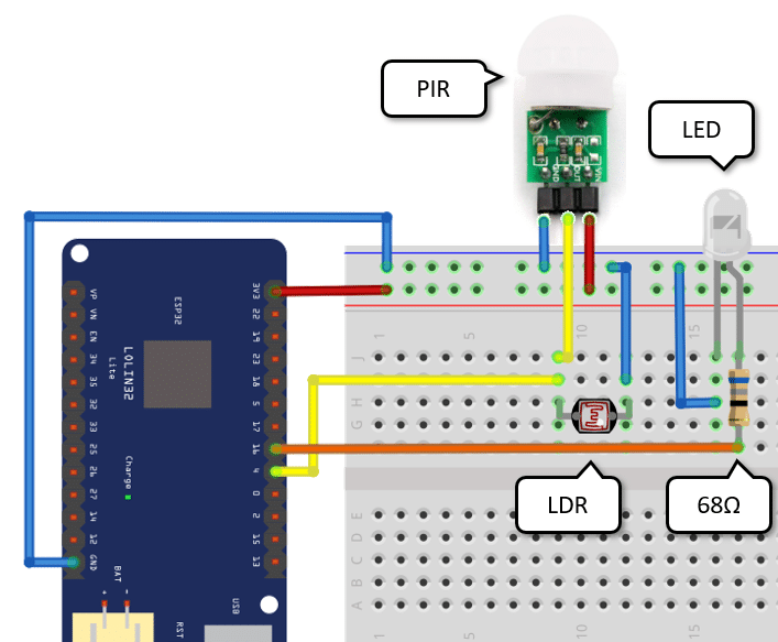
You can find the detailed wiring table here.
| From | Pin | Wire color | To | Pin |
| ESP32 | 3.3V | Red | Breadboard | Positive rail |
| ESP32 | GND | Blue | Breadboard | Negative rail |
| PIR | GND | Blue | Breadboard | Negative rail |
| PIR | VIN | Red | Breadboard | Positive rail |
| PIR | Out/Signal | Yellow | Breadboard | LDR |
| Breadboard | LDR | Yellow | ESP32 | 4 |
| ESP32 | 16 | Orange | Resistor | Any |
| Resistor | Any | – | LED | Anode (long pin) |
| LED | Cathode (short pin) | Blue | Breadboard | Negative rail |
Now, for the code.
Code for a Simple Night Light
The good news is, you need to write very little code to control the night light. See below.
Firstly, we define two constants for the pins the motion sensor (PIR_PIN) and the LED (LED_PIN) are connected to. In the setup() function we set the PIR_PIN to input mode, because we read from it. And the LED_PIN, we set to output mode, since we write to it.
#define PIR_PIN GPIO_NUM_4
#define LED_PIN GPIO_NUM_16

void setup() {
  pinMode(PIR_PIN, INPUT);
  pinMode(LED_PIN, OUTPUT);
}

void loop() {
  esp_sleep_enable_ext0_wakeup(PIR_PIN, 1);
  digitalWrite(LED_PIN1, HIGH);
  delay(5000);
  esp_deep_sleep_start();
}
In the loop() function we want to put the ESP32 into deep-sleep mode, wake it up when motion is detected and then switch the LED on for a short time. For this purpose, we first specify which pin enables the wakeup via esp_sleep_enable_ext0_wakeup(PIR_PIN, 1). If the PIR_PIN goes high (=1) we wake the ESP32 up.
Note that not any pin can be used as wake up source. Only for for the following pins wake up is supported: 0, 2, 4, 12-15, 25-27, 32-39.
Every time we wake up, we switch on the LED via digitalWrite, let it be active for 5sec (5000ms) using delay, and then go back to deep sleep by calling esp_deep_sleep_start().
As you can see, the code is very simple. Using deep-sleep will save tremendous amounts of battery and allows us to run the night light for much longer.
Now, you have a very simple night light. In the next section we increase its brightness and add a dimming effect to make it more interesting.
Building a Brighter, Dimming Night Light
In this section we add a second LED to make the night light brighter, and also slowly reduce the brightness over time. This gives a person a warning that the light is about to go off.
Circuit for a Brighter, Dimming Night Light
The circuit is essentially the same as before. We just add a second LED that is controlled via Pin 17 on the ESP32. We choose to add the second LED to another output to avoid overloading the pin. The ESP32 happily provides current of 20mA on its output pins, which is fine for a single LED. But connecting multiple LEDs to one pin would result in a too high current! So we either use another pin, or a transistor to control multiple LEDs. Since we have many pins left, we opt for the simpler solution and just use a additional pin.
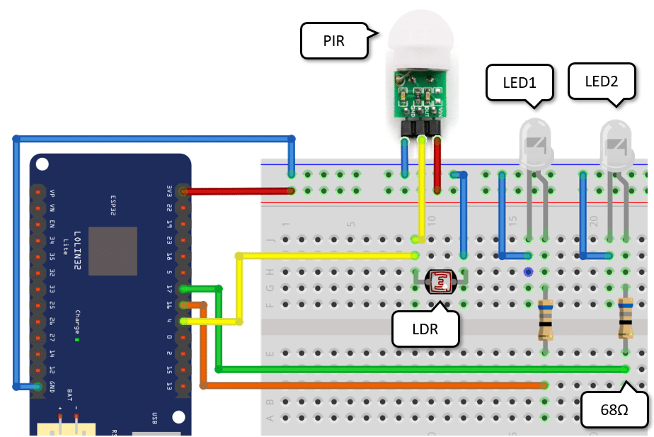
Below you will find the complete wiring table
| From | Pin | Wire color | To | Pin |
| ESP32 | 3.3V | Red | Breadboard | Positive rail |
| ESP32 | GND | Blue | Breadboard | Negative rail |
| PIR | GND | Blue | Breadboard | Negative rail |
| PIR | VIN | Red | Breadboard | Positive rail |
| PIR | Out/Signal | Yellow | Breadboard | LDR |
| Breadboard | LDR | Yellow | ESP32 | 4 |
| ESP32 | 16 | Orange | Resistor | Any |
| Resistor | Any | – | LED1 | Anode (long pin) |
| LED1 | Cathode (short pin) | Blue | Breadboard | Negative rail |
| ESP32 | 17 | Green | Resistor | Any |
| Resistor | Any | – | LED2 | Anode (long pin) |
| LED2 | Cathode (short pin) | Blue | Breadboard | Negative rail |
The code for this night light is a slight extension of the previous code. We will discussed in the next section.
Code for a Brighter, Dimming Night Light
First, we add another constant for the second LED (LED_PIN2). Then we add a new function fade() to dim the LEDs over time. To fade we reduce the brightness from the maximum of 255 to a low value of 50 in a loop. In each step we control the LEDs brightness via analogWrite and then wait for 100ms using delay(). So for 255-50 = 205 steps and with the delay of 100ms, it will take 20.5 seconds until the LEDs go dark.
For other possible lighting effect have a look at our tutorial on how to Control Halloween Lights using ESP32 on Battery, where we add a flickering effect.
#define PIR_PIN GPIO_NUM_4
#define LED_PIN1 GPIO_NUM_16
#define LED_PIN2 GPIO_NUM_17

void fade() {
  for(int brightness=255; brightness>50; brightness--) {
    analogWrite(LED_PIN1, brightness);
    analogWrite(LED_PIN2, brightness);
    delay(100);
  }
}

void setup() {
  pinMode(PIR_PIN, INPUT);
  pinMode(LED_PIN1, OUTPUT);
  pinMode(LED_PIN2, OUTPUT);
}

void loop() {
  esp_sleep_enable_ext0_wakeup(PIR_PIN, 1);
  fade();
  esp_deep_sleep_start();
}
Nothing really new happens in the setup() function. We just need to set the pin mode for the additional LED. Similarly, the loop() function remains largely unchanged. After specifying the wakeup source we call fade() to dim the LEDs and then initiate deep sleep.
Extensions
There are all possible kinds of extensions you could add to this basic implementation. For instance, we could ad a flickering effect at the end of the dimming period, as some commercial night lights do. We could use RGB LEDs for come color effect. Or we could use the motion sensor as an alarm system. If motion is detected, we activate the WiFi of the ESP32 and send an email. An alarm buzzer would be easy to incorporate as well.
Endless possibilities. For example, in the next section, I show you how to integrated this night light into a great looking skull.
Upload Code via Arduino IDE
If you use the same ESP32 board I listed in the required parts, select the WEMOS LOLIN32 Lite board and the correct COM port. Then press the upload (->) button.

A Skull as Night Light
We now have the circuit to build a motion activated night light and putting everything into a box with a battery would work just fine. But I wanted something a bit more exciting. So, I bought this anatomically correct mini-skull listed under required parts. It has a removable top and can easily fit all the hardware.
Below you can see a picture of the open skull and the circuit including the battery. I just had to widen the eye sockets and the nose a bit to fit in the LEDs and the motion sensor.
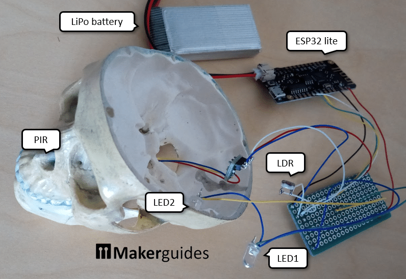
Note that I also repainted the sull and added some weathering effect. The end product looks great! You can see the motion sensor in the nose (the LEDs are still missing in this picture).

Finally, I extended the code for the fade() function a bit. I factored out the setting of brightness for the two leds and added a loop that makes the eyes blink three times at the end of the fading period. Another warning that the light is going to switch of very soon.
void set_leds(int brightness, int wait_ms) {
    analogWrite(LED_PIN1, brightness);
    analogWrite(LED_PIN2, brightness);
    delay(wait_ms);
}

void fade() {
  for(int brightness=255; brightness>50; brightness--) {
    set_leds(brightness, 100);
  }
  for(int i=0; i<3; i++) {
    set_leds(0, 500);
    set_leds(50, 500);
  }
}
I hope you enjoyed this project and have fun building your own night light.
Conclusion
In this tutorial, we have learned how to build a motion-activated night light using Arduino, PIR and LDR sensors. By combining the power of these components, we can create a convenient and energy-efficient lighting solution for our homes.
We started by understanding the working principles of both the light (LDR) and PIR sensors. The light sensor helps us detect the ambient light level, while the PIR sensor detects motion in its range. By combining these two sensors, we can create a system that only activates the night light when it’s dark and motion is detected.
We then went through the step-by-step process of building a simple night light. We connected the sensors and the relay module to the Arduino, and programmed it to control the light based on the sensor readings. This simple night light is perfect for illuminating small areas like hallways or bathrooms.
For those who want a more versatile night light, we also explored building a brighter, dimming night light. The dimming effect allows us to adjust the lighting level according to our preference.
Finally, we integrated the night light into a great looking skull.
In conclusion, building a motion-activated night light is a fun and practical project that can enhance the safety and convenience of your home.
Frequently Asked Questions
Here are some commonly asked questions about building a motion activated night light:
Q: How does a motion activated night light work?
A: A motion activated night light uses a combination of a light sensor (LDR) and a passive infrared (PIR) sensor to detect motion in the surrounding area. When motion is detected, and the light sensor detects low light levels, the light is turned on.
Q: What are the advantages of using a motion activated night light?
A: The main advantage of using a motion activated night light is energy efficiency. It only turns on when motion is detected, saving power compared to a traditional night light that remains on all night. Additionally, it provides convenience as it automatically illuminates the area when someone enters it.
Q: Can I adjust the sensitivity of the motion sensor?
A: Many motion sensors come with adjustable sensitivity settings. You can usually find a potentiometer or jumper on the sensor module that allows you to adjust the sensitivity. However, the AM312 does not offer this. Go for the larger HC-SR501 if you need this.
Q: How far can the motion sensor detect motion?
A: The range of motion detection depends on the specific motion sensor module you are using. Generally, most PIR sensors have a range of around 5 to 7 meters (16 to 23 feet). The AM312 used here has a shorter range of only 3-5 meters.
Q: Can I use multiple motion sensors for better coverage?
A: Yes, if you want to cover a larger area, you can use multiple motion sensors strategically placed around the space. This allows for better coverage and ensures that the night light turns on whenever motion is detected from any direction.
Q: Can I customize the brightness of the night light?
A: Yes, you can customize the brightness of the night light by adjusting the code to control the brightness level.
Q: Can I use this project with an Arduino or other ESP32 board?
A: Absolutely! This project is compatible with Arduino, ESP32, and similar microcontroller boards. However, if you want to run the night light on battery, look for a board with low power consumption.
Q: Do I absolutely need a microcontroller?
A: No, if you use the more advanced HC-SR501 motion sensor it will be sufficient for simple night light. The HC-SR501 supports an LDR to detect light levels and has an adjustable activation times. Add a battery and you have a functional night light. However, the HC-SR501 has no dimming effect and cannot be used as an alarm system without additional electronics.
If you have any more questions or need further assistance, feel free to ask in the comments section below.
Links
- Sensors for Arduino and other MCUs – A complete overview
- Arduino UNO And Light Sensor Project
- HC-SR501 PIR Motion Sensor Arduino Tutorial (3 Examples)
- Motion Detection with ESP32 & PIR Sensor
- ESP32 – Motion Sensor – LED
- ESP32 Arduino Tutorial: PIR motion sensor
- ESP32 with PIR Motion Sensor using Interrupts and Timers
- Deep Sleep — Arduino-ESP32 2.0.6 documentation
- ESP32 External Wake Up from Deep Sleep
- In-Depth: ESP32 Deep Sleep & Wakeup Sources
- ESP32 WeMos LOLIN32 Lite high resolution pinout and specs
Stefan is a professional software developer and researcher. He has worked in robotics, bioinformatics, image/audio processing and education at Siemens, IBM and Google. He specializes in AI and machine learning and has a keen interest in DIY projects involving Arduino and 3D printing.