In this article, we will learn how to use the MQ-2 gas sensor with an Arduino to display gas levels on an OLED display. The MQ-2 Gas Sensor is a universal gas sensor that can detect various gases such as methane, butane, propane, alcohol, smoke, and more. By connecting the MQ-2 sensor to an Arduino and displaying the gas levels on an OLED display, we can easily monitor the ambient gas levels in our surroundings.
In the following sections, we will discuss the required parts for this project, provide an introduction to the MQ-2 sensor, explain how to connect the parts together, and guide you through writing the Arduino code. Finally, we will conclude by summarizing the key points and addressing some frequently asked questions.
If you are interested in building a gas level monitoring system using the MQ-2 Universal Gas Sensor and Arduino, then keep reading!
Required Parts
Below you will find the parts required for this project. If you already have a resistor set and some LEDs you will not need the suggested kit. Only a single red LED and a 220 Ohm resistor are needed for this specific project.

Arduino Uno

Dupont Wire Set

Breadboard

USB Cable for Arduino UNO
OLED Display
MQ-2 Gas Sensor
Makerguides.com is a participant in the Amazon Services LLC Associates Program, an affiliate advertising program designed to provide a means for sites to earn advertising fees by advertising and linking to products on Amazon.com. As an Amazon Associate we earn from qualifying purchases.
Introducing the MQ-2
The MQ-2 is a fairly universal gas sensor that can detect various gases such as methane, propane, butane, alcohol, smoke, and more. It has a high sensitivity and a fast response time.
In contrast to the MQ-2, the other sensors in the MQ series are optimized for detecting specific types of gases. For instance:
- MQ-3: Designed primarily for detecting alcohol.
- MQ-4: Designed primarily for detecting methane and natural gas.
- MQ-5: Designed for LPG and natural gas.
- MQ-6: Designed specifically for LPG detection.
- MQ-7: Focused on carbon monoxide (CO) detection.
- MQ-8: Primarily for hydrogen gas detection.
- MQ-9: Detects carbon monoxide (CO) and flammable gases.
Note that we have tutorials for some of these sensors:
- How to use the MQ-2 Gas Sensor with Arduino and an OLED
- Air Pollution Monitoring and Alert System Using Arduino and mq135
- MQ3 Sensor & Arduino: Building An Alcohol Detector
- Using the MQ4 Methane Gas Sensor With Arduino Made Easy
Technical specs of the MQ-2 Gas Sensor
Below you will find the technical specifications of the MQ-2 Gas Sensor:
- Operating Voltage: 5V DC
- Heater Voltage: 5V DC
- Power Consumption: Approximately 150mA
- Sensing Resistance: 2KΩ to 20KΩ in clean air
- Sensitivity: Adjustable through a potentiometer
- Preheat Time: Approximately 48 hours
- Response Time: Less than 10 seconds
- Recovery Time: Less than 30 seconds
- Operating Temperature: -10°C to 50°C
- Operating Humidity: 95% RH (non-condensing)
Note that these specifications may vary slightly depending on the manufacturer and version of the MQ-2 Gas Sensor.
Internals of the MQ-2 Gas Sensor
In this section we look at the internal workings of the MQ-2 sensor. The sensor uses a layer composed of a metal oxide (SnO2). When gas comes into contact with this layer, it reacts with the oxygen present on the surface of the SnO2. This results in a change in resistance.
The picture below is taken from the datasheet of the MQ-2 sensor and show its components and internal circuitry.
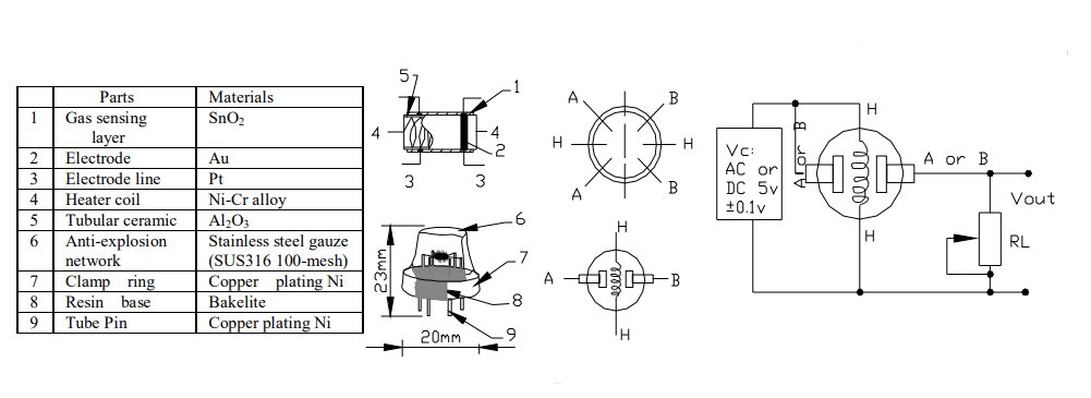
If you look closely you can see that the sensing layer (1) is wrapped in a heater coil (4). It provides the heat needed for the chemical reaction of the gas with SnO2 to occur. The heating element is the reason, why you will feel that the sensor gets warm in operation.
Around the sensing layer and the heater coil is a tubular ceramic (5) for physical protection and thermal insulation. The mesh on top (6) ensures that the gas doesn’t explode due to the heater.
Finally, we have the electrodes (2, 3), made of gold (Au) and platinum (Pt). They are attached to the sensing layer. The electrodes measure the changes in the resistance of the sensing layer.
Sensitivity Characteristics of the MQ-2 Gas Sensor
The MQ-2 gas sensor is designed to detect gases such as LPG (liquefied petroleum gas), methane (CH4), propane, alcohol, hydrogen (H2), smoke, and carbon monoxide (CO). As you can see in the diagram below, its sensitivity is largely uniform across these gases (same slope).
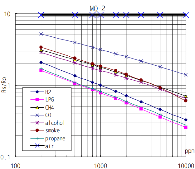
The sensor’s sensitivity refers to the ratio (Rs/Ro) of the sensor resistance in various gases to the sensor resistance in clean air. You can see the more gas is present (higher ppm) the lower the resistance.
Humidity and Temperature Dependency of the MQ-2 Gas Sensor
Note, however, that the MQ-2 gas sensor is influenced by ambient humidity and temperature. The following graph shows the change in resistance depending on ambient temperature and humidity.
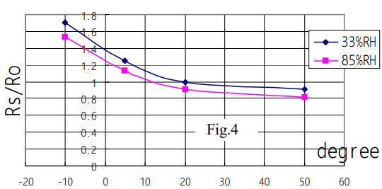
Humidity can affect the sensor’s performance, mainly because the water vapor can occupy the active sites on the tin dioxide (SnO2) sensing layer where gas detection reactions occur.
Temperature is another factor to consider when using the MQ-2 gas sensor. The MQ-2 sensor includes a built-in heater to maintain the necessary temperature for the SnO2 sensing layer. However, ambient temperature can still influence the sensor readings.
If you need accurate and stable readings, you may need additional temperature and a humidity sensors to compensate for those dependencies. Also note, that the MQ-2 needs to heat up for at least 20 seconds before its readings become stable and reliable.
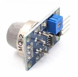
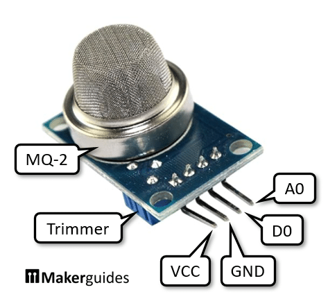
MQ-2 Gas Sensors Pinout
Instead of using the raw MQ-2 sensor it is easier to use one of the MQ-2 modules, such as the one listed above. These module have four pins for easy interfacing with the microcontroller. The VCC pin is for the 5V power supply and the GND pin needs to be connected to ground. The A0 pin provides the analog output voltage proportional to the gas concentration. And the D0 pin outputs a digital signal (HIGH or LOW).
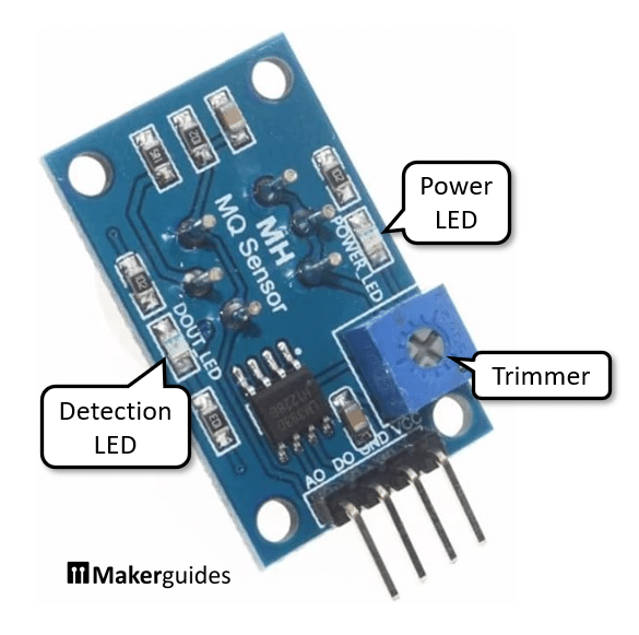
On the backside of the module you will find a trimmer to adjust the switching threshold for D0. There you also see a power LED (red) that is lit when the module has power. In addition, there is a detection LED (green) that comes on when gas is detected (D0=HIGH) above the trimmer-set threshold.
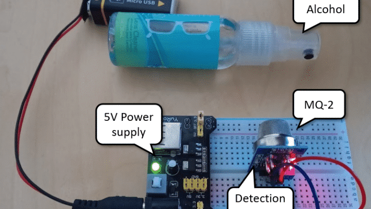
Testing the MQ-2 Gas Sensor
You can easily test the function of the module even without an Arduino. Connect VCC and GND to a 5V power supply and the red power LED at the back of the module should come on. Now wait a few seconds (for stable readings >20 seconds). You will notice that the sensor module gets slightly warm due to the heating element.
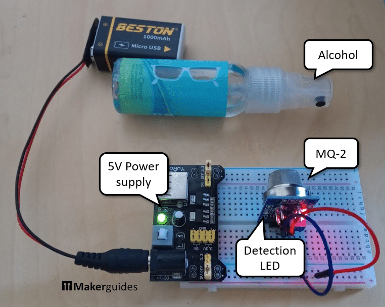
If you spray a bit of alcohol (screen cleaner, perfume, …) in front of the sensor the green detection LED will come on. If not, adjust the trimmer at the back of the module. You can also try the gas from a lighter.
In the next section, we will discuss how to connect the MQ-2 Gas Sensor with Arduino and write the necessary code to start detecting methane gas.
Connecting the Parts
In this section we will connect the MQ-2 sensor and the OLED display. First, let’s connect power from the Arduino to the power rails of the breadboard (red and blue wire from 5V and GND pin). Then connect power from the power rails to MQ-2 sensor and the OLED display (red and blue wires).
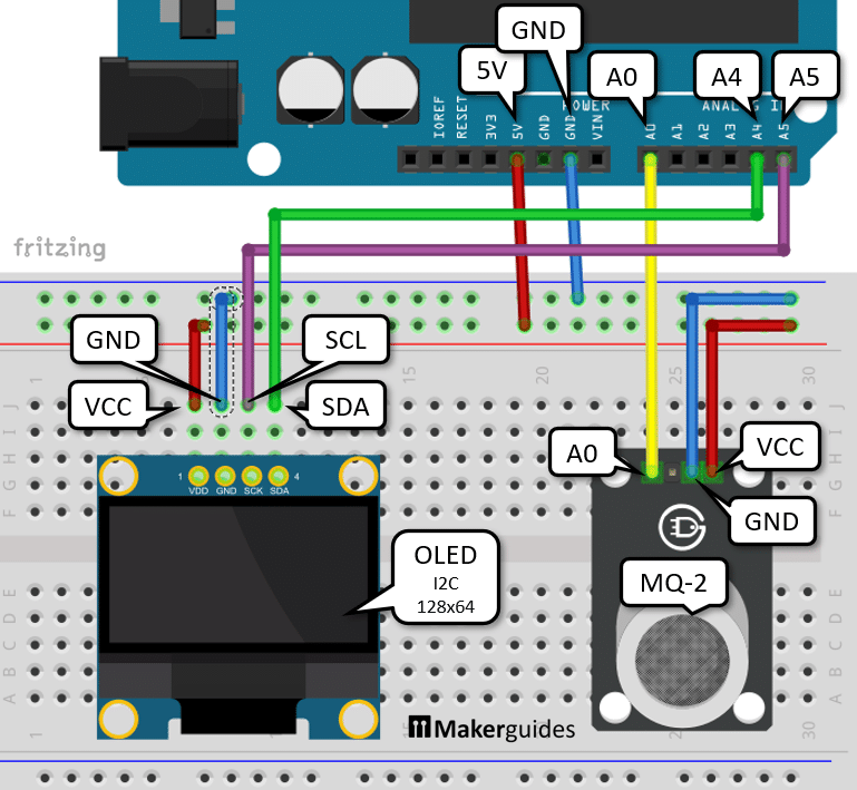
But watch out! There are two versions the SDD1306 OLED 128×64 display, with the VCC and GND pins swapped! Make sure to connect VCC to +5V (or +3V3, which works as well). If you need more details on how connect and use the OLED have a look at our tutorial on How to Interface the SSD1306 I2C OLED Graphic Display.
After that connect analog output A0 of the MQ-2 sensor the analog input A0 of the Arduino (yellow wire). Finally we need to connect the I2C pins SCL and SDA to the A4 and A5 inputs of the Arduino (purple and green wires, SCL->A5, SDA->A4).
That completes the connection of the parts. If you need more details regarding the wiring of the components have a look at the table below.
| From | Pin | Wire color | To | Pin |
| Arduino | 5V | Red | Breadboard | Positive rail |
| Arduino | GND | Blue | Breadboard | Negative rail |
| MQ-2 | GND | Blue | Breadboard | Negative rail |
| MQ-2 | VCC | Red | Breadboard | Positive rail |
| MQ-2 | Out/Signal/A0 | Yellow | Arduino | A0 |
| OLED | VCC | Red | Breadboard | Positive rail |
| OLED | GND | Blue | Breadboard | Negative rail |
| OLED | SCL | Purple | Arduino | A5 |
| OLED | SDA | Green | Arduino | A4 |
In the next section we are going to write the code to display the measured gas levels on the OLED display.
Writing the Arduino Code
The code below reads data from an MQ-2 sensor and displays the sensor value on an OLED display. It runs continuously, updating the display every second with a new sensor value.
#include "Wire.h"
#include "Adafruit_GFX.h"
#include "Adafruit_SSD1306.h"

#define SCREEN_WIDTH 128
#define SCREEN_HEIGHT 64
#define SCREEN_ADDRESS 0x3C

Adafruit_SSD1306 display(SCREEN_WIDTH, SCREEN_HEIGHT, &Wire, -1);

void setup() {
  Serial.begin(115200);

  if(!display.begin(SSD1306_SWITCHCAPVCC, SCREEN_ADDRESS)) {
    Serial.println("Can't find display!");
    for(;;);
  }
  delay(100);
  display.setTextSize(5);
  display.setTextColor(WHITE);
}

void loop() {
  int sensorValue = analogRead(A0);
  Serial.print("Gas:");
  Serial.println(sensorValue);

  display.clearDisplay();
  display.setCursor(20, 16);
  display.println(sensorValue);
  display.display();

  delay(1000);
}
To understand the code in more detail, let’s have a look at its parts. We start with the libraries and constants.
Libraries and Constants
First we include the necessary libraries for the I2C communication with the OLED display.
#include "Wire.h"
#include "Adafruit_GFX.h"
#include "Adafruit_SSD1306.h"
After that we define the constants for screen width, height, and I2C address.
#define SCREEN_WIDTH 128
#define SCREEN_HEIGHT 64
#define SCREEN_ADDRESS 0x3C
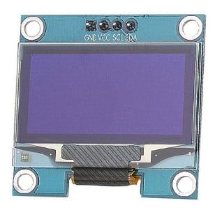
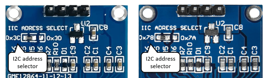
Watch out when looking for the I2C address of your display. Typically that address is 0x3C. If you are lucky, you will see this address at the back of OLED display module (left picture below). You could change the address by soldering the resistor to the second position.
There are other common OLED modules that show the I2C address on 0x78 on the back (right picture). This is misleading (it’s the 8-bit address in contrast to the 7-bit address you want). The I2C address for these displays is also 0x3C! Don’t get tricked by the labelling on the back.
If you can’t get it working and need to find the I2C address you can install the I2CScanner library to do so. Here is the code to run a scan. But make sure the display is correctly wired and powered.
#include "I2CScanner.h"

I2CScanner scanner;

void setup() {
  Serial.begin(9600);
  while (!Serial) {};

  scanner.Init();
}

void loop() {
  scanner.Scan();
  delay(5000);
}
Display object
In this line we create the display object using the constants defined above.
Adafruit_SSD1306 display(SCREEN_WIDTH, SCREEN_HEIGHT, &Wire, -1);
Display Setup
In the setup() function, we initialize the serial communication and start the OLED display. If the display is not found, we print an error message and enter an infinite loop.
void setup() {
  Serial.begin(115200);

  if(!display.begin(SSD1306_SWITCHCAPVCC, SCREEN_ADDRESS)) {
    Serial.println("Can't find display!");
    for(;;);
  }
  delay(100);
  display.setTextSize(5);
  display.setTextColor(WHITE);
}
Otherwise, we wait for a short period (100ms). And then set the text size to 5 and the text color to white. A text size of 5 will fill the display nicely.
Data Reading and Display
In the loop() function, we first read the analog value from pin A0, which is connected to the MQ-2 sensor. Then we print the gas level value to the serial monitor.
  int sensorValue = analogRead(A0);
  Serial.print("Gas:");
  Serial.println(sensorValue);
Next, we clear the OLED display, set the cursor position to (20, 16), which will print the MQ-2 sensor value roughly in the middle of the display. After that we print the sensor value on the display. However, the value will not appear until we update the display by calling display.display().
  display.clearDisplay();
  display.setCursor(20, 16);
  display.println(sensorValue);
  display.display();

  delay(1000);
Finally, we add a delay of 1 second before repeating the loop.
Output example
If you run this code and watch the Serial Plotter you should see a peak appearing, if you expose then MQ-2 sensor to some gas (perfume, screen cleaner, lighter) or smoke. The picture below shows the sensor response after exposed to the fumes of isopropyl alcohol (screen cleaner).
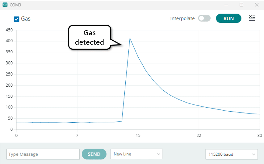
There you go. Now you can monitor gas levels and build a gas warning system!
Conclusion
In this tutorial, we have learned how to use the MQ-2 Universal Gas Sensor with Arduino. We started by introducing the required parts for this project, which include an Arduino board, the MQ-2 sensor, an OLED display, and a few jumper wires.
Next, we discussed the MQ-2 sensor in detail, explaining its functionality and the gases it can detect.
After that, we moved on to the practical aspect of the project and showed you how to connect the MQ-2 sensor to the Arduino board. We provided a clear wiring diagram and explained the purpose of each connection.
To make the sensor work, we then wrote a simple Arduino code that reads the analog output from the MQ-2 sensor and displays it on an OLED display. We explained the code step by step, making it easy to understand.
In conclusion, the MQ-2 Universal Gas Sensor is a versatile and affordable option for detecting various gases. With the help of an Arduino board, you can easily integrate this sensor into your projects and create gas monitoring systems.
We hope this tutorial has been helpful in getting you started with the MQ-2 sensor. If you have any further questions or need additional assistance, please refer to the Frequently Asked Questions section or leave a comment.
Happy experimenting with the MQ-2 Universal Gas Sensor and Arduino!
Frequently Asked Questions
Here are some commonly asked questions about using the MQ-2 Gas Sensor with Arduino:
Q: How does the MQ-2 Gas Sensor work?
The MQ-2 Gas Sensor works on the principle of gas conductivity. It contains a sensing element made of tin dioxide (SnO2) that reacts with gas. When gas is present, the conductivity of the sensing element increases, which can be measured by the Arduino.
Q: How accurate is the MQ-2 Gas Sensor?
The accuracy of the MQ-2 Gas Sensor can vary depending on various factors such as calibration, environmental conditions, and the concentration of the gas being detected.
Q: How can I calibrate the MQ-2 Gas Sensor?
To calibrate the MQ-2 Gas Sensor, you need to expose it to a known concentration of gas. The datasheet states:
We recommend that you calibrate the detector for 1000ppm liquified petroleum gas, or 1000ppm iso-butane concentration in air and use value of Load resistance that( RL) about 20 KΩ (5KΩ to 47 KΩ).
Q: Can I use the MQ-2 Gas Sensor for safety applications?
While the MQ-2 Gas Sensor can detect flammable gases, it is not certified for safety applications. It is primarily intended for educational, research, and prototyping purposes.
Q: Can I use the MQ-2 Gas Sensor with ESP32?
Yes, the MQ-2 Gas Sensor can be used with ESP32 as well. The wiring and code will be similar to using it with Arduino. However, make sure to check the voltage levels and pin compatibility between the sensor and the ESP32 board.
Q: Can I run the Gas Detection System on Batteries?
It is possible but requires rather large batteries and I would not recommend it. The MQ-2 sensor consumes about 150mA and needs to be warmed up for at least 30 seconds for reliable readings.
Q: What is the typical lifespan of the MQ-2 sensor?
The lifespan of the MQ-2 sensor can vary depending on usage and environmental conditions. On average, it can last for several years with proper care.
Q: Can I use the MQ-2 sensor in outdoor environments?
The MQ-2 sensor is not designed for outdoor use. It is recommended to use it in indoor environments where it can provide accurate gas detection.
Refer to the datasheet and documentation of the MQ-2 Gas Sensor for more detailed information and specifications.
Links
Here some other useful links regarding the MQ-2 sensor and how to use it with an Arduino.
- Arduino Smoke Detector with MQ-2 Gas/ Smoke sensor
- Guide for MQ-2 Gas/Smoke Sensor with Arduino
- Arduino MQ-2 Gas Sensor Tutorial
Stefan is a professional software developer and researcher. He has worked in robotics, bioinformatics, image/audio processing and education at Siemens, IBM and Google. He specializes in AI and machine learning and has a keen interest in DIY projects involving Arduino and 3D printing.