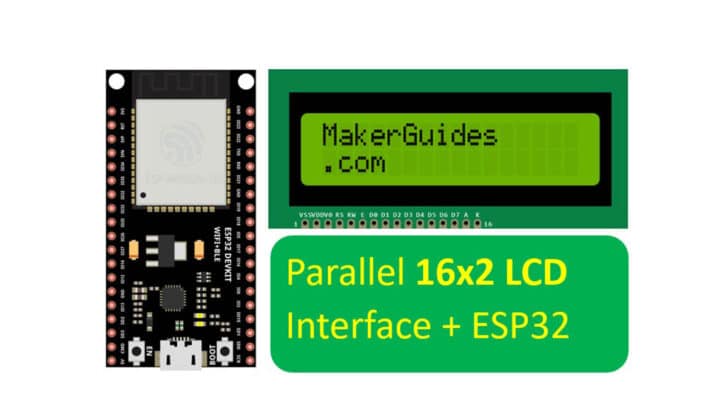
In this article, I will show you how to connect an ESP32 microcontroller to a 16×2 LCD display with a parallel data interface.
(In a separate article, I have already taught how to connect the ESP32 to the I2C 16×2 LCD – go check it out if you are looking for an I2C LCD with ESP32).
The parallel LCD accepts data from ESP32 over an eight-bit data line. We will only use 4 data bits. We cannot sometimes afford 8 data lines; the LCD also supports a 4-bit data interface, which is what I will show you in this tutorial.
I will start by taking you through the LCD controller Integrated Circuit (IC) specifications, share a few tips and tricks, and show you how to display random characters and look at possible applications.
I’ll then go into more detail and share a connection guide, ESP32 code for the 16×2 LCD parallel data interface, and answer some frequently asked questions about using a 16×2 LCD with an ESP32.
Grab your ESP32, and let’s get started!
Components Needed To Build ESP32 And 16×2 LCD Project
Hardware Components
- Dupont wire x 1 set
- Micro USB Cable for ESP32 (for powering ESP32 and programming) x 1
Software
Guide
Makerguides.com is a participant in the Amazon Services LLC Associates Program, an affiliate advertising program designed to provide a means for sites to earn advertising fees by advertising and linking to products on Amazon.com.
Fundamentals Of The 16×2 LCD Displays
Let us understand the features of the 16×2 LCD and the built-in LCD controller.
The HD44780U 16×2 LCD is a dot matrix liquid crystal display driver, with the following key features:
| Parameter | Range |
| Matrix supported | 5 x 8, and 5 x 10 |
| Operating voltage | 2.7 V to 5.5 V |
| High-speed bus interface | Up to 2 MHz |
| Number of data bits | 4-bit and 8-bit data interface |
| Display RAM | 80 x 8-bit display RAM |
| Character fonts | 208 ( 5 x 8 dot) 32 ( 5 x 10 dot) |
| Duty cycle | Programmable (⅛, 1/11, 1/16) |
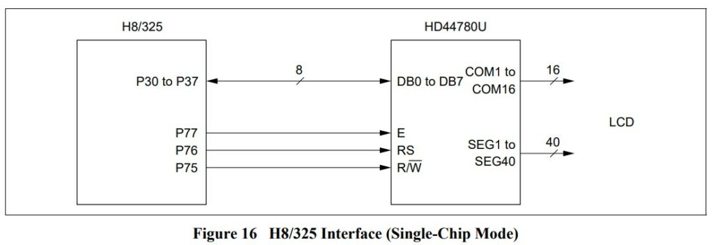
A typical connection between a Microcontroller Unit (MCU) and the display controller is shown below:
I want to begin by teaching you about CGROM and CGRAM of the LCD.
CGROM and CGRAM
CGROM (Character Generator ROM)
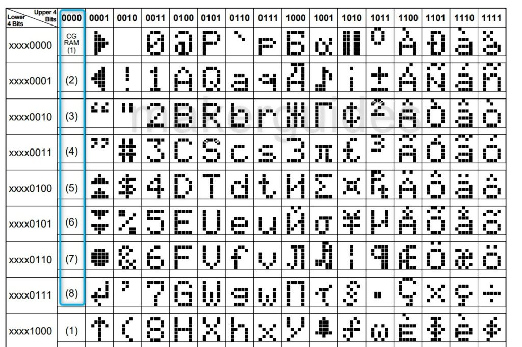
Based on 8-bit character codes, the CGROM generates character patterns in either a 5×8 dot or a 5×10 dot format.
In the 5×8 dot format, this ROM can produce 208 character patterns, and in the 5×10 dot format, 32 character patterns.
A mask-programmed ROM can also be used to construct user-defined character patterns. These come from factory predefined. You cannot change the during run time.
CGROM (Character Generator ROM)
You can rewrite character patterns using a program in the character generator RAM.
Eight character patterns may be created for 5×8 dots, while four can be produced for 5×10 dots.
To display the character patterns recorded in CGRAM, enter the character codes at the addresses listed in the left column into DDRAM.
The correlation between CGRAM addresses, data, and display patterns is below.
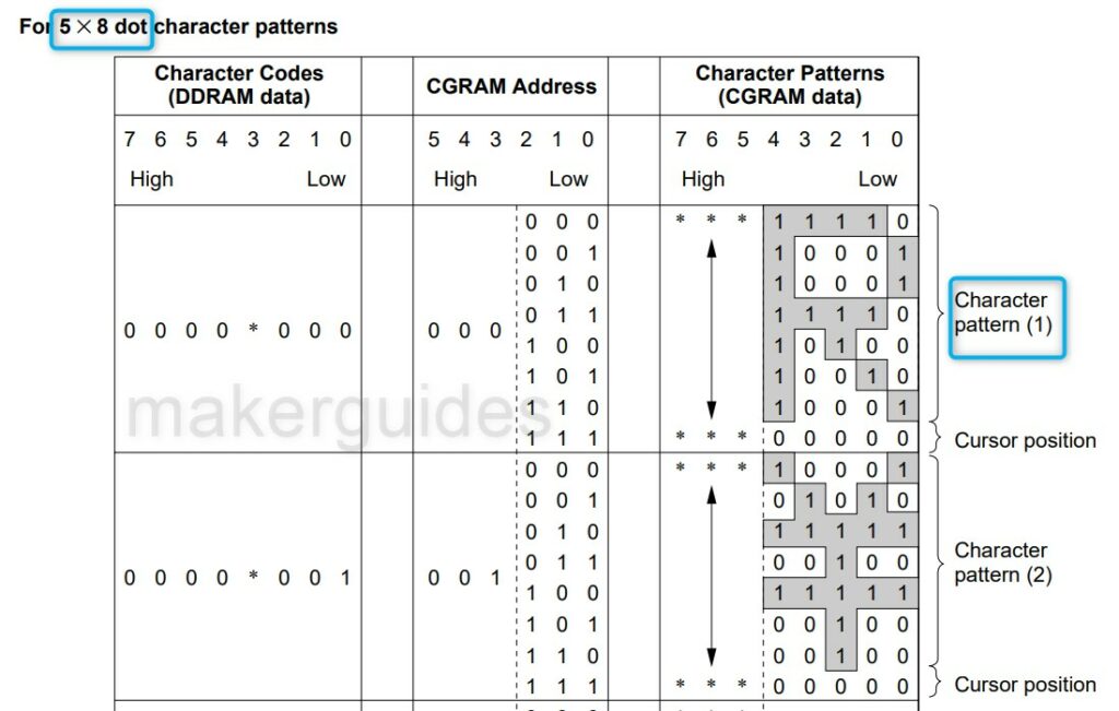
General data RAM can be employed in areas not used for displays.
Refer to the I2C LCD Article, where you can see more examples of how to program your characters!
Interfacing the LCD controller to the MCU
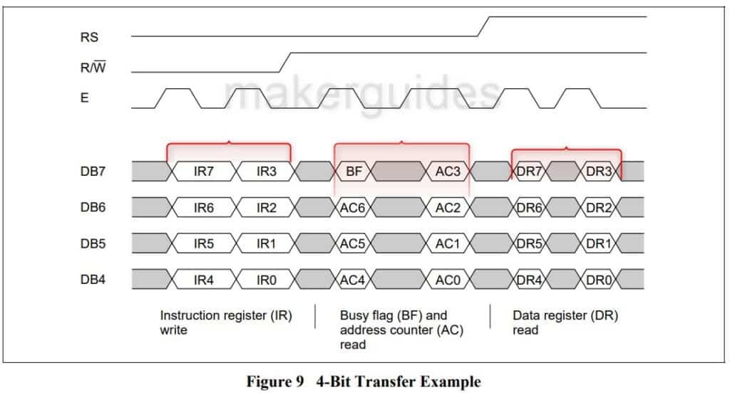
4-bit interface
Used only four data lines (DB to DB7). DB0 to DB3 bus lines are disabled. The data transfer between the HD44780U and the MPU is completed after the 4-bit data has been transferred twice.
8-bit interface
For 8-bit interface data, all eight bus lines (DB0 to DB7) are used.
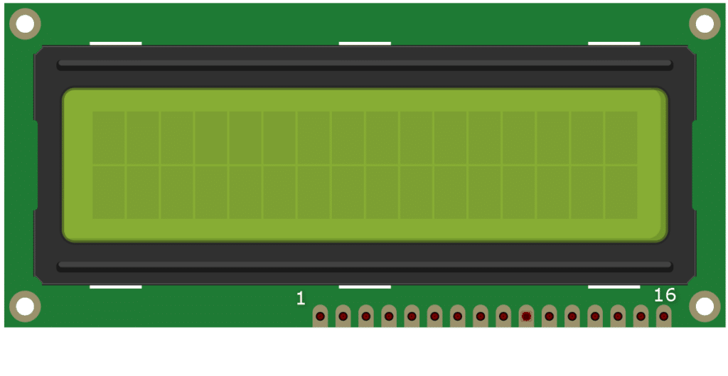
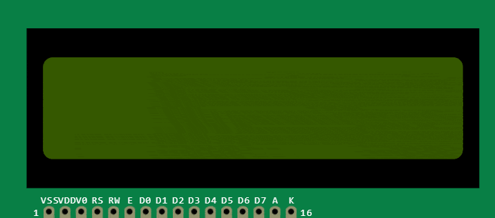
Pin definition of 16×2 LCD Module
Here is the pin description of the LCD module. Let’s begin.
| Pin Number | Pin Name | LCD Pin Description |
| 1 | VSS | Ground connections |
| 2 | VDD | 5 V supply connection |
| 3 | V0 | Contrast adjust pin (connect pot’s center pin here) |
| 4 | RS | Register Select 0: Instruction register (for write) busy flag: address counter (for read) 1: Data register (for write and read) |
| 5 | RW | Ground (always WRITE mode only) 0: Write1: Read |
| 6 | E | Enable the LCD controller |
| 7 | D0 | Data bit 0 (Not used during 4-bit operation) |
| 8 | D1 | Data bit 1 (Not used during 4-bit operation) |
| 9 | D2 | Data bit 2 (Not used during 4-bit operation) |
| 10 | D3 | Data bit 3 (Not used during 4-bit operation) |
| 11 | D4 | Data bit 4 |
| 12 | D5 | Data bit 5 |
| 13 | D6 | Data bit 6 |
| 14 | D7 | Data bit 7 |
| 15 | A | LED backlight Positive |
| 16 | K | LED backlight Negative |
Applications of 16×2 LCD Modules
If you want the cheapest low-power and easy-to-program display, 16×2 LCDs are the go-to solution. Here’s a list of common applications you can use them in:
- To display time, day of the week, and timers or counters – I have personally used LCD for this purpose on an intelligent metering system. I used to display kW consumption, and with a button, the user could change the display content to show day, time, units consumed, and more.
- Sensor data display – Weather information, air quality, and other sensor data can readily be displayed on the LCDs. It helps to remove dependency on a laptop (for serial terminal) or mobile (Bluetooth).
The simplest solution is to plug in an LCD module. You can have a switch to toggle the power to the LCD when you don’t need it. So power saving plus comfort both.
- LCDs in the home automation system help you understand the status of various sensors, lights, appliances, etc. It also helps to have an LCD to see what we are entering.
- The LCD acts as a rugged long-term solution in industries, especially in harsh environments. The LCDs can read the machine status and configure a few settings faster.
- During the development of projects, too, you can print a few variables and the status of GPIOs on the LCD. It will help you to understand what is happening with the system.
You don’t have to connect the debugger or multimeters. In some cases, you will not have those luxuries during testing. LCDs are your friend during those situations.
- An exciting application is a dedicated message display board displaying random motivational quotes – Consider a Geek birthday gift.
Instructions To Connect The 16×2 LCD To ESP32
I will show you how to build a project using ESP32 and the 16×2 LCD. Let’s get started with the hardware connections. We will use a 4-bit data interface to talk to the LCD.
Step 1: Complete the ESP32 and LCD 16×2 hardware connections
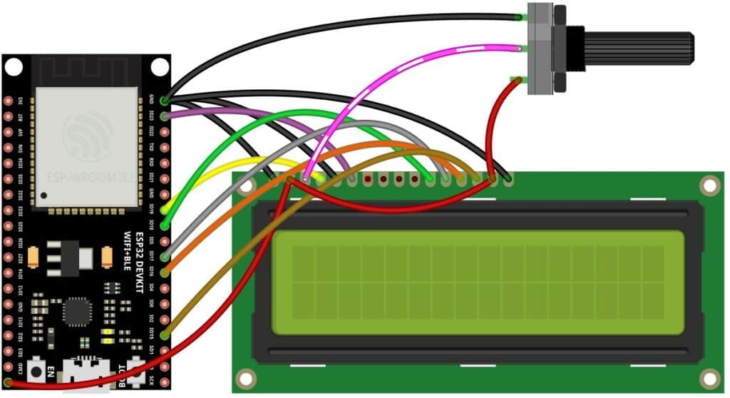
Here is the table summarizing the LCD and ESP32 connections. Please use the table below as a guide and connect the LCD pins to the ESP32 pins one by one.
| LCD Pin | LCD Label | ESP32 Pins |
| PIN 01 | VSS | GND |
| PIN 02 | VDD | 5 V |
| PIN 03 | V0 | 10 k Pot ( center pin) |
| PIN 04 | RS | GPIO19 |
| PIN 05 | RW | GND |
| PIN 06 | E | GPIO23 |
| PIN 07 | D0 | Not used |
| PIN 08 | D1 | Not used |
| PIN 09 | D2 | Not used |
| PIN 10 | D3 | Not used |
| PIN 11 | D4 | GPIO18 |
| PIN 12 | D5 | GPIO17 |
| PIN 13 | D6 | GPIO16 |
| PIN 14 | D7 | GPIO15 |
| PIN 15 | A | 5 V |
| PIN 16 | K | GND |
LCD interface using the following pins on ESP32. The potentiometer is used to control the contrast of the display. If you skip the potentiometer, you might see nothing on the display.
A potentiometer is an excellent solution to set the contrast and avoid unnecessary troubles.
You should remember that contrast is not set and try debugging the connections. Unlike the I2C interface, the parallel interface uses several wires.
Step 2: Program the ESP32 with the code below
Follow the next step to understand the code implementation. You can use the code below to test the 16×2 LCD interface with a parallel data interface module and the connected ESP32.
// include the library code:
#include "LiquidCrystal.h"


// initialize the library with the numbers of the interface pins
LiquidCrystal lcd(19, 23, 18, 17, 16, 15);


void setup() {
  // set up the LCD's number of columns and rows:
  lcd.begin(16, 2);
  // Print a message to the LCD.
  lcd.print("MakerGuides.");
}


void loop() {
  // set the cursor to column 0, line 1
  // (note: line 1 is the second row, since counting begins with 0):
  lcd.setCursor(0, 1);
  // print the number of seconds since reset:
  lcd.print(millis() / 1000);
}
Step 3: Code Walkthrough
Let’s walk through the code. This example tests a connected 16×2 LCD. The code is used to display custom messages on the LCD.
#include "LiquidCrystal.h"
This line includes the LiquidCrystal library in the code. It allows us to use functions that communicate with an LCD screen.
LiquidCrystal lcd(19, 23, 18, 17, 16, 15);
This line initializes the LCD object with the specified interface pins. The six arguments in the parentheses represent the pins connected to the RS, E, D4, D5, D6, and D7 pins of the LCD, respectively.
void setup() {
  // set up the LCD's number of columns and rows:
  lcd.begin(16, 2);
  // Print a message to the LCD.
  lcd.print("circuitschools.");
}
The setup() function is called only once when the ESP32 board is powered up or reset. Here, we are initializing the LCD with the begin() function.
The function sets the number of columns and rows for the LCD screen.
In the example, we set the LCD to be 16 columns and two rows. Next, we are printing the string “MakerGuides.” on the first row of the LCD screen.
void loop() {
  // set the cursor to column 0, line 1
  // (note: line 1 is the second row, since counting begins with 0):
  lcd.setCursor(0, 1);
  // print the number of seconds since reset:
  lcd.print(millis() / 1000);
}
The loop() function is called repeatedly after the `setup()` function. Here, we are setting the cursor to the first column of the second row (i.e., line 1), and printing the number of seconds that have passed since the ESP32 board was powered up or reset.
The millis() function returns the number of milliseconds that have elapsed since the board was last reset, and we divide it by 1000 to convert it to seconds before printing it on the LCD.
I hope the code explanation helped. I hope you will use a 16×2 LCD in the near future in your upcoming projects.
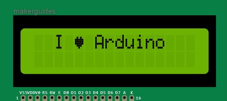
Example 2: Create a Heart Pattern
The code below creates a heart pattern.
// https://wokwi.com/projects/294395602645549578
#include "LiquidCrystal.h"


LiquidCrystal lcd(12, 11, 10, 9, 8, 7);


uint8_t heart[8] = {
  0b00000,
  0b01010,
  0b11111,
  0b11111,
  0b11111,
  0b01110,
  0b00100,
  0b00000,
};


void setup() {
  lcd.createChar(3, heart);
  lcd.begin(16, 2);
  lcd.print("  I \x03 Arduino");
}


void loop() { }
Example 3: Create an Animation
This example provides you with an example of how creative you can get using the CGRAM feature.
Source code:
/*
    butterfly metamorphosis animation
    https://projecthub.arduino.cc/tusindfryd/57d77608-cd7e-4d6a-b52f-7a604cc121c5

    2021 ~ by   tusindfryd
    this code is in public domain
*/


#include <LiquidCrystal.h>
LiquidCrystal   lcd(12, 11, 5, 4, 3, 2); // RS, E, D4, D5, D6, D7
void setup()
{
  lcd.begin(16,   2);
}
void loop()
{
  image00();
  delay(250);
  image01();
  delay(250);
  image02();
  delay(250);
  image03();
  delay(700);
  image04();
  delay(250);
  image05();
  delay(250);
  image06();
  delay(700);
  image07();
  delay(1250);
}


void image00()
{
  lcd.clear();


  byte image22[8] = {B00110, B01101, B11011, B10011, B00111,   B01111, B01111, B11111};
  byte image23[8] = {B01111, B11110, B11100, B11000,   B11000, B10000, B10000, B00000};
  byte image07[8] = {B00000, B00000, B00000,   B00000, B00000, B00000, B00001, B00111};
  byte image08[8] = {B00000, B01000,   B10000, B10000, B10000, B11111, B11111, B11000};
  byte image09[8] = {B00000,   B00000, B00000, B00000, B00000, B11000, B11000, B00100};


  lcd.createChar(0,   image22);
  lcd.createChar(1, image23);
  lcd.createChar(2, image07);
  lcd.createChar(3, image08);
  lcd.createChar(4, image09);


  lcd.setCursor(5,   1);
  lcd.write(byte(0));
  lcd.setCursor(6, 1);
  lcd.write(byte(1));
  lcd.setCursor(6, 0);
  lcd.write(byte(2));
  lcd.setCursor(7, 0);
  lcd.write(byte(3));
  lcd.setCursor(8, 0);
  lcd.write(byte(4));
}


void   image01()
{
  lcd.clear();


  byte image22[8] = {B00110, B00101,   B00011, B00011, B00111, B01111, B01111, B11111};
  byte image23[8] = {B01111,   B11110, B11100, B11000, B11000, B10000, B10000, B00000};
  byte image07[8]   = {B00000, B00000, B00000, B00000, B00000, B00000, B11001, B10111};
  byte   image08[8] = {B00000, B01000, B10000, B10000, B10000, B11111, B11111, B11000};
  byte image09[8] = {B00000, B00000, B00000, B00000, B00000, B11000, B11000, B00100};
  byte image06[8] = {B00000, B00000, B00000, B00000, B00000, B00000, B00000, B00011};


  lcd.createChar(0, image22);
  lcd.createChar(1, image23);
  lcd.createChar(2,   image07);
  lcd.createChar(3, image08);
  lcd.createChar(4, image09);
  lcd.createChar(5, image06);


  lcd.setCursor(5, 1);
  lcd.write(byte(0));
  lcd.setCursor(6, 1);
  lcd.write(byte(1));
  lcd.setCursor(6, 0);
  lcd.write(byte(2));
  lcd.setCursor(7, 0);
  lcd.write(byte(3));
  lcd.setCursor(8, 0);
  lcd.write(byte(4));
  lcd.setCursor(5, 0);
  lcd.write(byte(5));
}


void image02()
{
  lcd.clear();


  byte image22[8] = {B00000, B00001, B00011, B00011, B00111, B01111, B01111, B11111};
  byte image23[8] = {B01111, B11110, B11100, B11000, B11000, B10000, B10000, B00000};
  byte image07[8] = {B00000, B00000, B00000, B00001, B00111, B00100, B11001, B10111};
  byte image08[8] = {B00000, B01000, B10000, B10000, B10000, B11111, B11111, B11000};
  byte image09[8] = {B00000, B00000, B00000, B00000, B00000, B11000, B11000, B00100};


  lcd.createChar(0, image22);
  lcd.createChar(1, image23);
  lcd.createChar(2,   image07);
  lcd.createChar(3, image08);
  lcd.createChar(4, image09);


  lcd.setCursor(5, 1);
  lcd.write(byte(0));
  lcd.setCursor(6, 1);
  lcd.write(byte(1));
  lcd.setCursor(6, 0);
  lcd.write(byte(2));
  lcd.setCursor(7, 0);
  lcd.write(byte(3));
  lcd.setCursor(8, 0);
  lcd.write(byte(4));
}


void image03()
{
  lcd.clear();


  byte image22[8] = {B00000, B00001, B00011, B00011, B00111, B01111, B01111, B11111};
  byte image23[8] = {B01111, B11110, B11100, B11000, B11000, B10000, B10000, B00000};
  byte image07[8] = {B00000, B00000, B00000, B00000, B00000, B00000, B00001, B00111};
  byte image08[8] = {B00000, B01000, B10000, B10000, B10000, B11111, B11111, B11010};
  byte image09[8] = {B00000, B00000, B00000, B00000, B00000, B11000, B11000, B00100};
  byte image24[8] = {B00010, B00111, B00111, B00111, B00111, B00111, B00010, B00000};


  lcd.createChar(0, image22);
  lcd.createChar(1, image23);
  lcd.createChar(2,   image07);
  lcd.createChar(3, image08);
  lcd.createChar(4, image09);
  lcd.createChar(5, image24);


  lcd.setCursor(5, 1);
  lcd.write(byte(0));
  lcd.setCursor(6, 1);
  lcd.write(byte(1));
  lcd.setCursor(6, 0);
  lcd.write(byte(2));
  lcd.setCursor(7, 0);
  lcd.write(byte(3));
  lcd.setCursor(8, 0);
  lcd.write(byte(4));
  lcd.setCursor(7, 1);
  lcd.write(byte(5));
}


void image04()
{
  lcd.clear();


  byte image22[8] = {B00000, B00001, B00011, B00011, B00111, B01111, B01111, B11111};
  byte image23[8] = {B01111, B11110, B11100, B11000, B11000, B10001, B10000, B00000};
  byte image07[8] = {B00000, B00000, B00000, B00000, B00000, B00000, B00001, B00111};
  byte image08[8] = {B00000, B01000, B10000, B10000, B10000, B11111, B11111, B11010};
  byte image09[8] = {B00000, B00000, B00000, B00000, B00000, B11000, B11000, B00100};
  byte image24[8] = {B00010, B00100, B01011, B10101, B11010, B10101, B11010, B01110};
  byte image25[8] = {B00000, B00000, B00000, B10000, B10000, B00000, B00000, B00000};


  lcd.createChar(0, image22);
  lcd.createChar(1, image23);
  lcd.createChar(2,   image07);
  lcd.createChar(3, image08);
  lcd.createChar(4, image09);
  lcd.createChar(5, image24);
  lcd.createChar(6, image25);


  lcd.setCursor(5,   1);
  lcd.write(byte(0));
  lcd.setCursor(6, 1);
  lcd.write(byte(1));
  lcd.setCursor(6, 0);
  lcd.write(byte(2));
  lcd.setCursor(7, 0);
  lcd.write(byte(3));
  lcd.setCursor(8, 0);
  lcd.write(byte(4));
  lcd.setCursor(7, 1);
  lcd.write(byte(5));
  lcd.setCursor(8, 1);
  lcd.write(byte(6));
}


void image05()
{
  lcd.clear();


  byte image24[8] = {B01010, B10100, B01011, B10101, B11010, B10101, B11010, B01110};
  byte image25[8] = {B00000, B00000, B00000, B10000, B10000, B00000, B00000, B00000};
  byte image23[8] = {B01101, B01010, B01101, B00111, B00000, B00000, B00000, B00000};
  byte image07[8] = {B00000, B00000, B00000, B00000, B00000, B00000, B00001, B00011};
  byte image08[8] = {B00000, B00000, B00000, B00000, B00000, B00000, B00000, B10000};


  lcd.createChar(0, image24);
  lcd.createChar(1, image25);
  lcd.createChar(2,   image23);
  lcd.createChar(3, image07);
  lcd.createChar(4, image08);


  lcd.setCursor(7, 1);
  lcd.write(byte(0));
  lcd.setCursor(8, 1);
  lcd.write(byte(1));
  lcd.setCursor(6, 1);
  lcd.write(byte(2));
  lcd.setCursor(6, 0);
  lcd.write(byte(3));
  lcd.setCursor(7, 0);
  lcd.write(byte(4));
}


void image06()
{
  lcd.clear();


  byte image08[8] = {B00000, B00100, B01010, B01010, B10001, B00011, B00110, B01100};
  byte image07[8] = {B00000, B00000, B00000, B00000, B00001, B00010, B00010, B00001};
  byte image09[8] = {B00000, B00000, B10000, B11000, B00000, B00000, B11000, B00100};
  byte image24[8] = {B00100, B00100, B00011, B00000, B00000, B00000, B00000, B00000};
  byte image25[8] = {B10000, B00000, B00000, B00000, B00000, B00000, B00000, B00000};


  lcd.createChar(0, image08);
  lcd.createChar(1, image07);
  lcd.createChar(2,   image09);
  lcd.createChar(3, image24);
  lcd.createChar(4, image25);


  lcd.setCursor(7, 0);
  lcd.write(byte(0));
  lcd.setCursor(6, 0);
  lcd.write(byte(1));
  lcd.setCursor(8, 0);
  lcd.write(byte(2));
  lcd.setCursor(7, 1);
  lcd.write(byte(3));
  lcd.setCursor(8, 1);
  lcd.write(byte(4));
}


void image07()
{
  lcd.clear();


  byte image24[8] = {B10101, B01110, B01110, B00100, B10101, B01110, B00100, B11111};
  byte image08[8] = {B00000, B00100, B01010, B01010, B10001, B00011, B00110, B01100};
  byte image07[8] = {B00000, B00000, B00000, B00000, B00001, B00010, B00010, B00001};
  byte image09[8] = {B00000, B00000, B10000, B11000, B00000, B00000, B00000, B00000};


  lcd.createChar(0, image24);
  lcd.createChar(1, image08);
  lcd.createChar(2,   image07);
  lcd.createChar(3, image09);


  lcd.setCursor(7, 1);
  lcd.write(byte(0));
  lcd.setCursor(7, 0);
  lcd.write(byte(1));
  lcd.setCursor(6, 0);
  lcd.write(byte(2));
  lcd.setCursor(8, 0);
  lcd.write(byte(3));
}
FAQs About The 16×2 LCD And ESP32 Projects
I have included a list of the most frequently asked questions about projects built using the ESP32 and the 16×2 LCD module.
What is a 16×2 parallel data LCD?
A 16×2 parallel data LCD with 16 characters in each row for 32 characters. It is controlled by a microcontroller such as Arduino or an ESP32 using a parallel interface. It involves sending data to the LCD one byte at a time through data pins.
What interface pins are required to connect a 16×2 parallel data LCD to a microcontroller?
A 16×2 parallel data LCD typically requires six interface pins connected to a microcontroller. These pins include RS (Register Select), E (Enable), D4, D5, D6, and D7.
How do I initialize and display text on a 16×2 LCD?
To initialize a 16×2 parallel data LCD, include the LiquidCrystal library in your code, create an instance of the LiquidCrystal class with the appropriate interface pins, and call the begin() function to set the number of rows and columns for the LCD.
To display text on the LCD, you can use the print() function to send the text to the LCD one character at a time. Please refer to the connection instructions section of the article.
How do you set the cursor position on a 16×2 LCD?
To set the cursor position on a 16×2 parallel data LCD, you can use the setCursor() function, which takes two arguments: the column number (0-15) and the row number (0-1).
Can you use a 16×2 LCD with a microcontroller that doesn’t have enough pins?
You can use an I2C interface module to reduce the interface pins required to control a 16×2 parallel data LCD. The module acts as an intermediary between the LCD and the microcontroller, converting the parallel data to serial data that can be transmitted using only two interface pins.
Conclusion
This article has covered all the essential information about using the 16×2 LCD with an ESP32 microcontroller.
I have given you complete information on working the 16×2 LCD module.
Knowing the complete information about how commands work, how data is framed, and the sequences needed to initiate LCD and write to the LCD can help you get creative with your displays and also debug your code if it goes wrong.
I also shared an ESP32 connection guide and example code with explanations explaining how the code works.
Was the article easy to follow? If you have suggestions to improve the article, you are always welcome to share feedback.
I’d love to hear from you! Let us know if there’s anything else you’d like me to cover in future articles.

I am Puneeth. I love tinkering with open-source projects, Arduino, ESP32, Pi and more. I have worked with many different Arduino boards and currently I am exploring, Arduino powered LoRa, Power line communication and IoT.