In this tutorial, you will learn all the essential details about the nRF24L01 transceiver module and how to use it to communicate wirelessly with Arduino boards.
We’ll look at how the nRF24L01 transceiver works and how to connect it to Arduino with pinout diagrams and example code for you to use.
After this tutorial, you will be able to develop the wireless communication between two Arduino boards using the nRF24L01 transceiver modules.
Hardware components
| Arduino Uno Rev3 | x1 | Amazon |
| Arduino Mega (Optional) | x1 | Amazon |
| nRF24L01 module | x1 | Amazon |
| LED | x1 | Amazon |
| Button switch | x1 | Amazon |
| 220Ω Resistor | x1 | Amazon |
| Breadboard | x1 | Amazon |
| Jumper wires | x10 | Amazon |
| USB cable type A/B | x1 | Amazon |
Software
| Arduino IDE | Arduino IDE |
Makerguides.com is a participant in the Amazon Services LLC Associates Program, an affiliate advertising program designed to provide a means for sites to earn advertising fees by advertising and linking to products on Amazon.com.
Introduction to nRF24L01
Using the nRF24L01 transceiver module, two or more microcontroller boards that have no wireless facilities can communicate with each other wirelessly over a distance.
nRF24L01 operates at the 2.4GHz ISM band and is used for wireless communication.
What is the nRF24L01 transceiver module?
The NRF24L01 wireless Transceiver RF module is cheap, and it is a Half-Duplex type module, which means it can either send or receive data at a time.
This module can cover 100 meters (200 feet) whenever it operates efficiently.
Although the module’s operating voltage ranges from 1.9V to 3.6V, it has 5V tolerant pins so that you can connect them directly to the Arduino.
If you want more technical details, check the: nRF24L01 datasheet.
nRF24L01 transceiver module specifications and features:
The NRF24L01 specifications and features are given below.
- The frequency is 2.4GHz ISM.
- The Nominal current is 50mA.
- 250mA is the maximum operating current.
- It can operate with baud rates from 250Kbps up to 2 Mbps.
- The module consists of a single chip GFSK transceiver with OSI link layer hardware.
- It provides auto ACK, retransmits, address, and CRC computation.
- It gives a short switching time, enabling frequency hopping.
- It has on the chip voltage regulator
- It has Enhanced ShockBurst™ protocol
- Automatic packet handling
- 6 data pipe MultiCeiver™
- Uses ultra ± 60 PPM 16MHz crystal
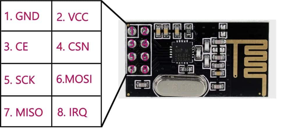
nRF24L01 Transceiver Module Pinout
nRF24L01 Transceiver Module has 8 pins available, which are used for data sent or received.
| Pin | Description |
| GND | This pin is the Ground Pin. |
| VCC | This pin supplies power for the module. It can be anywhere from 1.9 to 3.9 volts. |
| CE (Chip Enable) | This pin is an active-HIGH pin. When selected, the nRF24L01 will either transmit or receive, depending on its current mode. |
| CSN | This pin is an active-LOW pin and is usually kept HIGH. When this pin goes low, the nRF24L01 begins listening on its SPI port for data and processes it accordingly. |
| SCK (Serial Clock) | The only SPI bus Master that provides clock pulses. |
| MOSI (Master Out Slave In) | This pin is SPI input to the nRF24L01. |
| MISO (Master In Slave Out) | This pin is SPI output from the nRF24L01 module. |
| IRQ (Interrupt) | This pin is an interrupt pin that can alert the master when new data is available to process. |
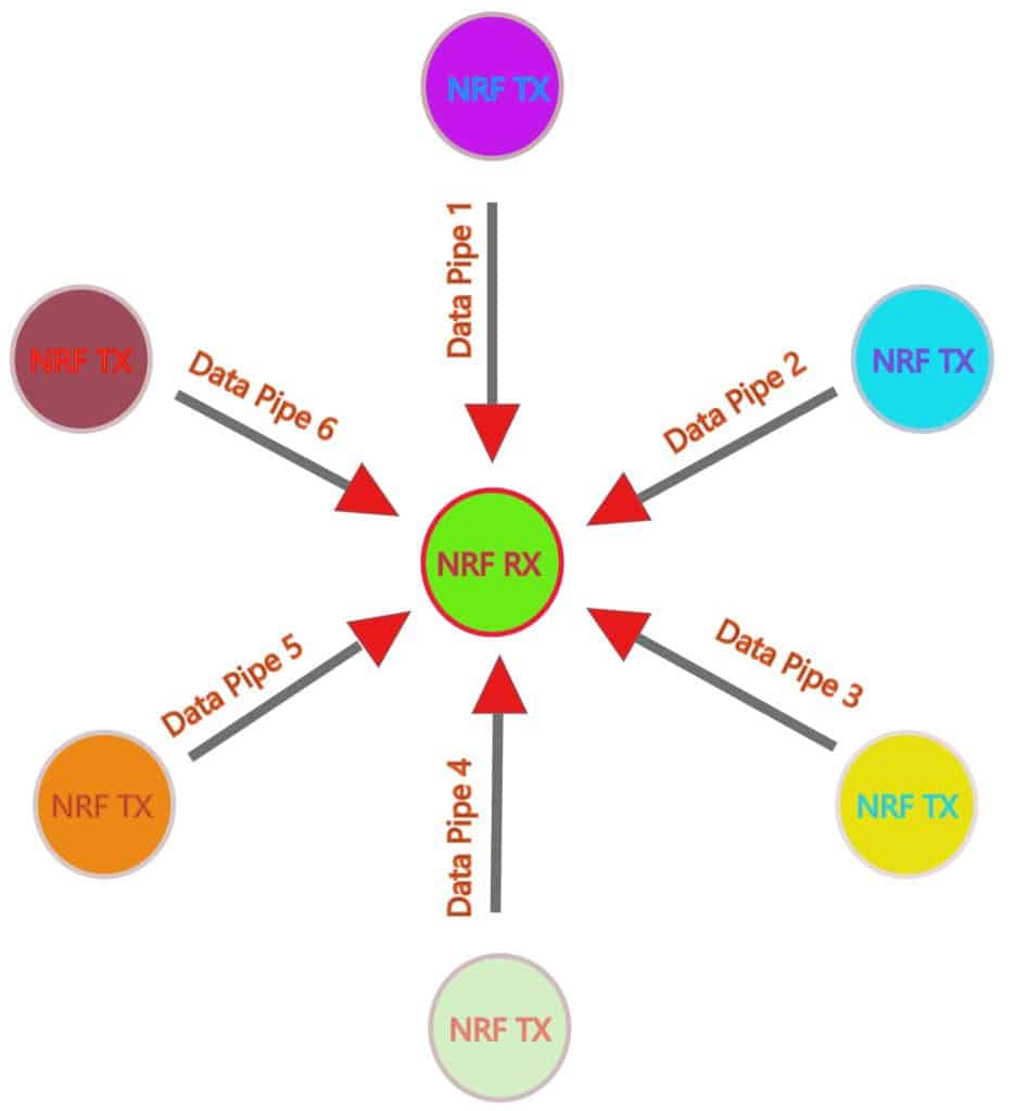
How nRF24L01 Transceiver RF module Works
The nRF24L01 Transceiver RF module has an address range of 125 to communicate with the other 6 modules and allows several wireless units to communicate simultaneously in a specified location.
Each channel occupies a bandwidth of less than 1MHz.
The nRF24L01 module uses the SPI (Serial Peripheral Interface) slave communication protocol with a maximum data rate of 10Mbps.
These SPI pins depend on microcontrollers.
Applications of the NRF24L01 Wireless Transceiver Module:
- Wireless Control System Applications
- Mesh Networks
- Drones remote control
- Robot control and monitoring
- Remote sensors for temperature, pressure, alarms, etc
- Telemetry
- Intelligent sports equipment
- Toys industries
- Automotive applications
- Security and alarm systems
- Home automation systems
- Wireless Keyboard and mouse, Joysticks
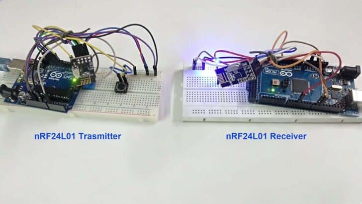
How to Connect the nRF24L01 to Arduino?
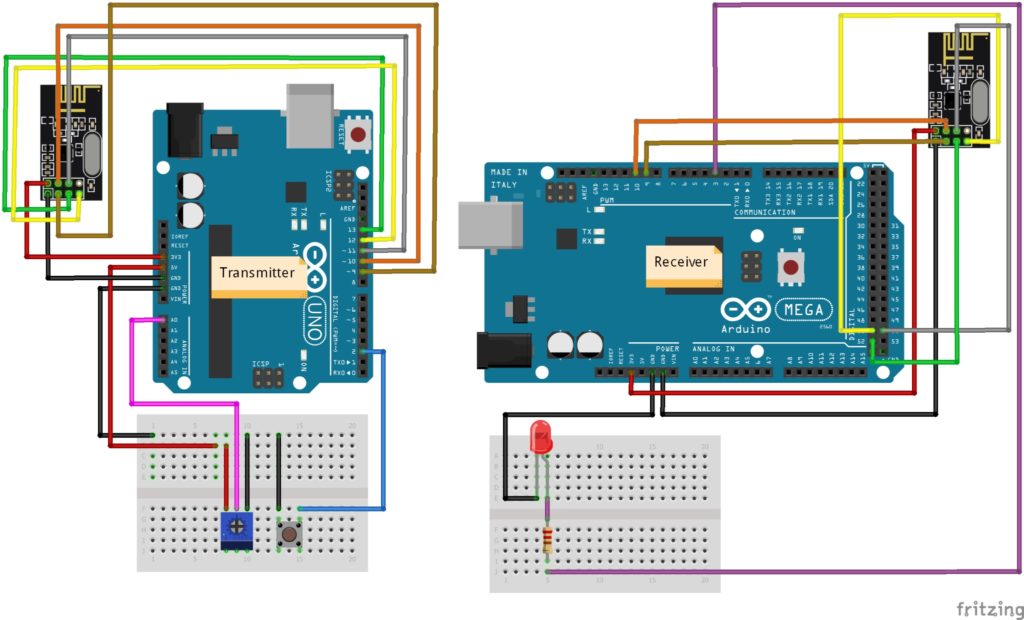
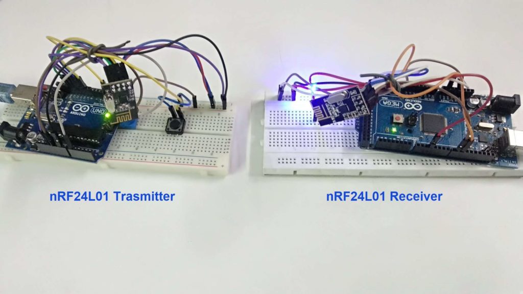
Here, I’m using an Arduino Uno Board used as a Transmitter and Arduino Mega Board used as a Receiver.
Now, follow the below-mentioned steps to connect the nRF24L01 Transceiver module and other components with the Arduino Board.
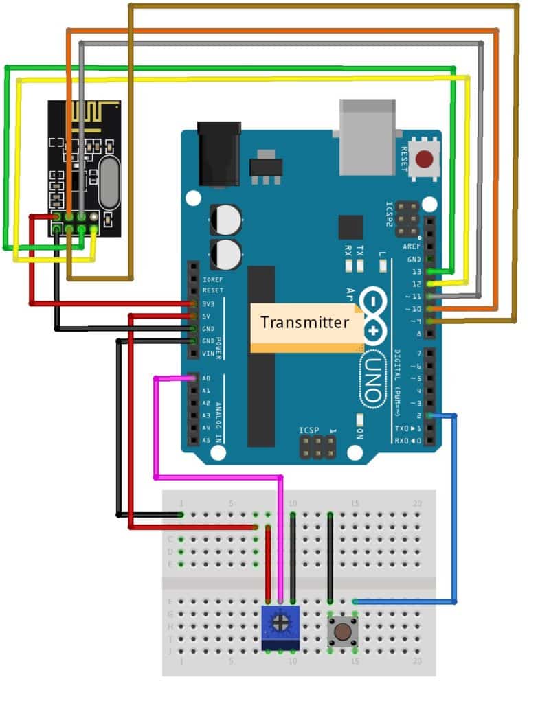
Wiring diagram of nRF24L01 module with Arduino Uno as Transmitter
Step 1: Connect Arduino Uno to nRF24L01 as mentioned in the table.
| Arduino Uno | nRF24L01 |
| MISO (12) | MISO (6) |
| MOSI (11) | MOSI (7) |
| SCK (13) | SCK (5) |
| Digital Pin 9 | CE (3) |
| Digital Pin 10 | CSN (4) |
| +3.3V | VCC (2) |
| GND | GND (1) |
Step 2: Plug the push button in the middle of the breadboard. Connect one side to the ground and the other side to digital pin 2 of Arduino Uno.
Step 3: Connect the 1st terminal of POT to the GND and the 3rd terminal of POT to +5V VCC on the Arduino Uno Board.
Connect the 2nd terminal of POT to the A0 pin of the Arduino Uno board. You read the output from terminal 2 of the potentiometer.
Make sure that all grounds are common.
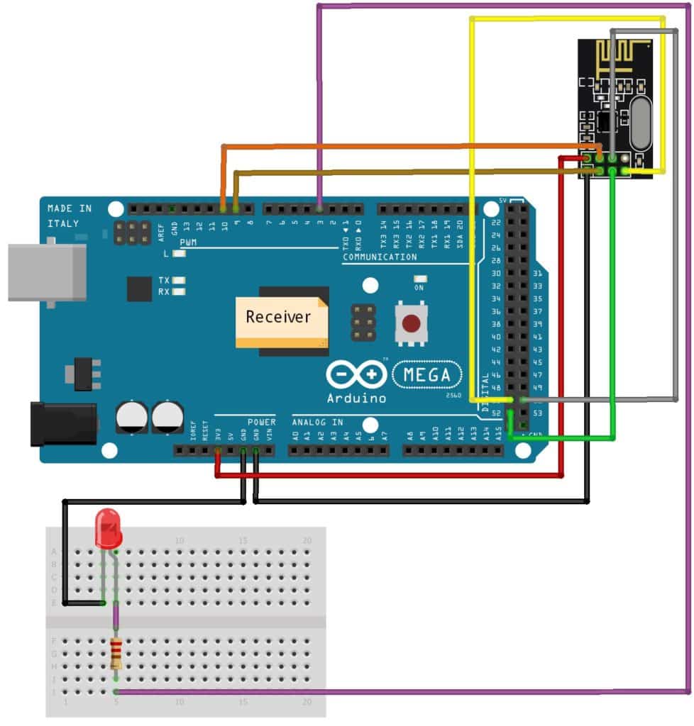
Wiring diagram of nRF24L01 module with Arduino Mega as Receiver
Step 1: Connect Arduino Mega to nRF24L01 as mentioned in the table.
| Arduino Mega | Or Arduino Uno | nRF24L01 |
| MISO (50) | MISO (12) | MISO (6) |
| MOSI (51) | MOSI (11) | MOSI (7) |
| SCK (52) | SCK (13) | SCK (5) |
| Digital Pin 9 | Digital Pin 9 | CE (3) |
| Digital Pin 10 | Digital Pin 10 | CSN (4) |
| +3.3V | +3.3V | VCC (2) |
| GND | GND | GND (1) |
Step 2: Connect the LED cathode (-) to the Ground, and the Anode (+) of the LED to the 220 Ohm resistor to digital pin 3 of the Arduino Mega Board.
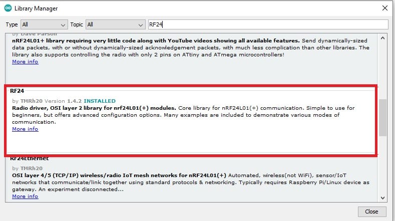
Installing the required Arduino library for nRF24L01
To use the nRF24L01 module with Arduino IDE, you can use an already built library from RF24.h.
Follow the below-mentioned steps to install the RF24.h library in Arduino IDE.
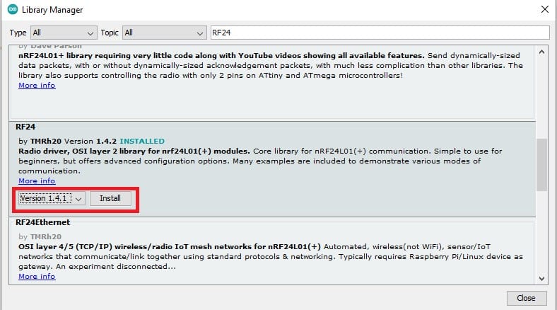
Step 1: Go to the Tools > Manage Libraries to open the library manager in Arduino IDE.

Step 2: Now, in the search box, type “RF24” and select the RF24.h library, install the latest version and use it.
Arduino Code for nRF24L01 (Transmitter with Potentiometer)
#include "SPI.h"
#include "nRF24L01.h"
#include "RF24.h"

#define CE_PIN   9
#define CSN_PIN 10
#define pot_pin A0

RF24 radio(CE_PIN, CSN_PIN);

const byte addresses [][6] = {"00001", "00002"};  //Setting the two addresses. One for transmitting and one for receiving
int button_pin = 2;

volatile int button_state = 0;
volatile int last_button_state = 0;
volatile int pot_flag = 0;

String str;
char pass[] = "A1B1";
char rx[5];
char pass_key[4] = {};

void setup() {
  pinMode(button_pin, INPUT_PULLUP);
  pinMode(pot_pin, INPUT);
  Serial.begin(9600);
  Serial.println("System Init");
  radio.begin();                           //Starting the radio communication
  radio.openWritingPipe(addresses[1]);     //Setting the address at send the data
  radio.openReadingPipe(1, addresses[0]);  //Setting the address at received the data
  radio.setPALevel(RF24_PA_MIN); //You can set it as minimum or maximum depending on the distance between the transmitter and receiver.
}

void loop()
{
  button_state = digitalRead(button_pin);
  if (button_state != last_button_state ) {
    if (button_state == LOW) {
      Serial.println("Enter your Password");
L1:      while (!Serial.available());
      {
        str = Serial.readString();
        for (int i = 0; i < str.length(); i++)
        {
          pass_key[i] = str[i];
        }
      }
      radio.stopListening();          //This sets the module as transmitter
      delay(10);
      if ((str.equals("A2B2")))
      {
        radio.write(&pass_key, sizeof(pass_key));
        str[0] = '\0';
        pass_key[0] = '\0';
      }
      else
      {
        Serial.println("Please Enter Correct Password");
        str[0] = '\0';
        pass_key[0] = '\0';
        goto L1;
      }
    }
  }
  last_button_state = button_state;

  radio.startListening();                            //This sets the module as receiver

  if (radio.available()) {
    radio.read(&rx, sizeof(rx));
    delay(5);
    if ((strcmp(rx , pass) == 0) || ( pot_flag == 1))
    {
      Serial.println("Password Authentication Done !");
      while (1) {
        pot_flag = 1;
        int data = analogRead(pot_pin);
        radio.stopListening();
        radio.write(&data, sizeof(data));    // Sending data over NRF24L01
        Serial.print("Transmitting Data : ");
        Serial.println(data);     // Printing POT value on serial monitor
        delay(1000);
      }
    }
  }
}
How the nRF24L01 Transmitter Code Works
Step 1: First, I have included the required library and defined the required variables.
#include "SPI.h"
#include "nRF24L01.h"
#include "RF24.h"

#define CE_PIN   9
#define CSN_PIN 10
#define pot_pin A0
Step 2: RF24 radio(CE_PIN, CSN_PIN);
This radio object represents a modem connected to the Arduino. Arguments CE_PIN and CSN_PIN are digital PINs.
Step 3: const byte addresses [][6] = {“00001”, “00002”};
Next, create a byte array representing the address, and create two pipes or addresses for the bi-directional communication.
Step 4: void setup()
In the void setup function, Using the pinMode() function, the button is used as INPUT_PULLUP and the potentiometer set as an INPUT.
Serial.begin(); function set the baud rate at 9600 frequency.
radio.begin(); This function activates and Initializes the modem.
radio.openWritingPipe(addresses[1]); function, set the address of the transmitter.
radio.openReadingPipe(1, addresses[0]); function sets the same address as the receiver and enables communication between transmitter and receiver.
radio.setPALevel() function sets the Power Amplifier level. I set it to a minimum as my modules are very close.
Step 5: void loop()
In the void loop,
radio.stopListening() function which sets the module as transmitter.
radio.startListening() function which sets the module as receiver.
radio.write(&tx, sizeof(tx)) is used to send that message to the receiver.
Serial.readString() reads characters from the serial buffer into a String.
Strcmp and Str.equals function is used to compare the two password strings so that MCU can identify whether the entered password is correct or not.
The digitalRead() function reads the logic state at a pin.
radio.available() function, I check whether there is data to be received.
Remember, before going to be sent the data by radio, the first call to radio.stopListening() function, and read any data first call to radio.startListening() function.
First, It waits for the button state to below and then asks for a password, which is a receiver-side predefined password, “A2B2”. I entered the password using the serial terminal.
If the entered password is correct, the receiver side LED will blink five times.
The printing message on the serial terminal is “Password Authentication Done ! “, otherwise again asking for your correct password.
radio.startListening();
 if (radio.available()) {
    radio.read(&rx, sizeof(rx));
    delay(5);
    if ((strcmp(rx , pass) == 0) || ( pot_flag == 1))
    {
      Serial.println("Password Authentication Done !");
      while (1) {
        pot_flag = 1;
        int data = analogRead(pot_pin);
        radio.stopListening();
        radio.write(&data, sizeof(data));
        Serial.print("Transmitting Data : ");
        Serial.println(data);
        delay(1000);
      }
    }
  }
}
If the received password and input password are matched, then using the potentiometer, you can vary the LED’s brightness.
The most interesting thing is that the LED is connected to the receiver side.
Send the potentiometer value to the receiver side and the value print on the serial terminal.
Arduino Code for nRF24L01 (Receiver with LED)
#include "SPI.h"
#include "nRF24L01.h"
#include "RF24.h"

#define CE_PIN   9
#define CSN_PIN  10
#define led_pin 3

RF24 radio(CE_PIN, CSN_PIN);

const byte addresses [][6] = {"00001", "00002"};    //Setting the two addresses. One for transmitting and one for receiving

String str;
char pass[] = "A2B2";

char rx[5];
char pass_key[4] = {};
volatile int pot_flag = 0;
int rx_int = 0;

void setup() {
  pinMode(led_pin, OUTPUT);
  digitalWrite(led_pin, LOW);
  Serial.begin(9600);
  Serial.println("System Init");
  radio.begin();                            //Starting the radio communication
  radio.openWritingPipe(addresses[0]);      //Setting the address at send the data
  radio.openReadingPipe(1, addresses[1]);   //Setting the address at received the data
  radio.setPALevel(RF24_PA_MIN);            //You can set it as minimum or maximum depending on the distance between the transmitter and receiver.
}

void loop() {
  radio.startListening();                    //This sets the module as receiver
  if (radio.available())
  {
    {
      rx[0] = 0;
      radio.read(&rx, sizeof(rx));
    }
    if (strcmp(rx , pass) == 0)
    {
      Serial.println("Password Authentication Done !");
      Serial.println("LED BLINK");
      for (int i = 0; i < 5; i++) {
        digitalWrite(led_pin, HIGH);
        delay(100);
        digitalWrite(led_pin, LOW);
        delay(100);
      }
      radio.stopListening();                           //This sets the module as transmitter
      delay(10);
      Serial.println("Enter your Password");
L1:      while (!Serial.available());
      {
        str = Serial.readString();
        for (int i = 0; i < str.length(); i++)
        {
          pass_key[i] = str[i];
        }
      }
      if ((str.equals("A1B1")))
      {
        radio.write(&pass_key, sizeof(pass_key));
        pot_flag = 1;
        str[0] = '\0';
        pass_key[0] = '\0';
      }
      else
      {
        Serial.println("Please Enter Correct Password");
        str[0] = '\0';
        pass_key[0] = '\0';
        goto L1;
      }
    }

    if (pot_flag == 1)
    {
      radio.startListening();
      while (1)
      {
        rx_int = 0;
        radio.read(&rx_int, sizeof(rx_int));
   Serial.print("Received Data : ");
   Serial.println(rx_int);      // Print received value on Serial Monitor
   analogWrite(led_pin , rx_int); // Write received value to pin 3 where LED is connected
   delay(1000);
      }
    }
  }
}
How the nRF24L01 Receiver Code Works
Step 1: First, I include the required library and define the variable.
#include "SPI.h"
#include "nRF24L01.h"
#include "RF24.h"

#define CE_PIN   9
#define CSN_PIN  10
#define led_pin 3
Step 2: void setup()
In the setup function, LED is set as an OUTPUT mode using the pinMode() function. And initialize the serial terminal and radio.
Step 3: void loop()
In the void loop(), If the radio is available, receive the transmitted data and compare it with a password.
If the password matches the serial terminal, print “Password Authentication Done! “The LED will blink five times.
Radio functions are the same as I explained in the transmitter side section.
Now, it will ask for the transmitter password to be sent to the transmitter. If your password is correct, then the communication will start.
Otherwise, it will ask for a valid password.
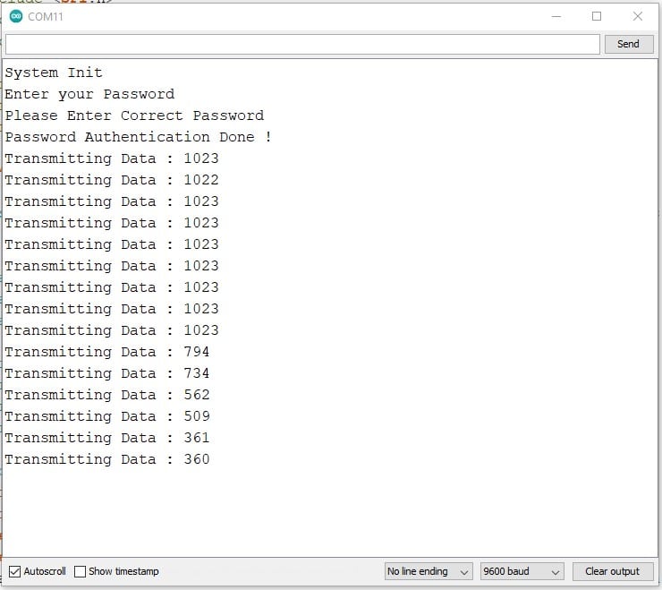
Output Of The Transmitter on the Serial Terminal
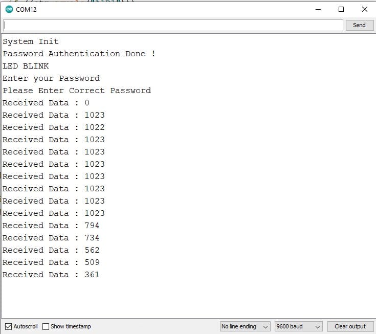
Output Of The Receiver on the Serial Terminal
Can nRF24L01 connect to WiFi?
It is not possible to connect to WiFi on the nRF24L01 module. Although nRF24L01 is used for wireless communication, the PHY layer on the nRF24L01+ and wifi are different.
Conclusion
After this tutorial, you can establish wireless communication between two nRF24L01 modules using Arduino boards.
Furthermore, you can control the brightness of the LED on the receiver side from the potentiometer on the transmitter side.
I hope you found this tutorial informative. If you did, please share it with a friend who likes electronics and making things!
I would love to know what project you plan on building or have already made with the Arduino.
If you have any questions or suggestions or think things are missing in this tutorial, please comment below.
Note that comments are held for moderation to prevent spam.

Hiren is a professional Embedded Engineer with a Master’s Degree
in Electronics and Communication Engineering. He is proficient in C and
C++ and enjoys building DIY projects on Arduino, ESP32, PIC32, STM32 & Raspberry PI boards.