In this article, I will show you how to connect a Bluetooth module HC-05 to an ESP32 microcontroller.
HC-05 enables you to connect any wired device to have wireless capability. It is a well-known Bluetooth module used with Arduino boards everywhere, and can be useful in certain situations for use with an ESP32 as well.
Why do you need an HC-05 Bluetooth module with an ESP32?
The latest ESP32 boards come with a built-in Bluetooth feature so you don’t need an HC-05 module in order to use Bluetooth with an ESP32.
However, there are use-cases, such as you are migrating from the Arduino board to the ESP32 board, but you want to keep the code the same (except for a few minor pin mappings).
Or maybe you want to avoid getting into Bluetooth-Low-Energy (BLE) features and more of ESP32 for a while. HC-05 helps you in these instances to get things rolling quickly.
I will teach you how to connect the HC-05 to an ESP32 and share some example codes you can use. I will show you all the valuable features and tricks of the HC-05 modules.
By the end of this article, you will understand how the ESP32 and HC-05 work and have the skills and knowledge to begin experimenting and integrating into your projects.
Whether you’re a beginner or an experienced maker, this article will provide a solid foundation to explore the world of HC-05 Bluetooth modules, and using them with an ESP32.
Let’s get started!
Components Needed To Build ESP32 And HC-05 Bluetooth Module Project
Hardware Components
- ESP32 Wroom 2.4 GHz with integrated Antenna x 1
- HC-05 Bluetooth Module x 1
- Dupont wire x 1 set
- Micro USB Cable for ESP32 (for powering ESP32 and programming) x 1
Software
Guide
Makerguides.com is a participant in the Amazon Services LLC Associates Program, an affiliate advertising program designed to provide a means for sites to earn advertising fees by advertising and linking to products on Amazon.com.
Introduction To The HC-05 Sensors
Before we see how to connect an HC-05 Bluetooth module to the ESP32, let’s take a look at the HC-05 Bluetooth module itself. In this section, I will teach you everything about HC-05 modules.
Right away, here is the link to the datasheet of the HC-05 module.
By the end of this article, you will be confident in building and debugging HC-05 Bluetooth modules in the future.
You will find a lot of HC-05 modules on the market.
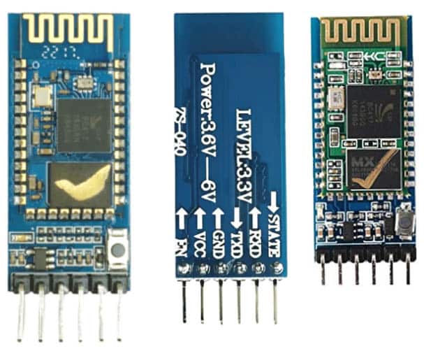
Eventually, if you look closer, they all contain the core System-On-A Chip (SoC) part, as shown in the image below.
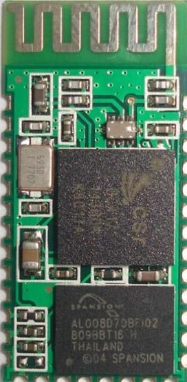
On its own it is cheaper, but there are better ideas than providing chips with castled pins for a hobbyist or a maker.
So, what we find in the market is a simple PCB added to the SoC to connect HC-05 to the breadboard and jumper cables easily.
HC-05 Pin Diagram
Here is an infographic of the pins and the details in an image. The below image provides you with pin details and pin functions of the HC-05 Bluetooth module:
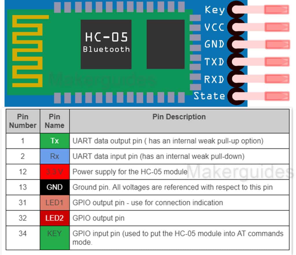
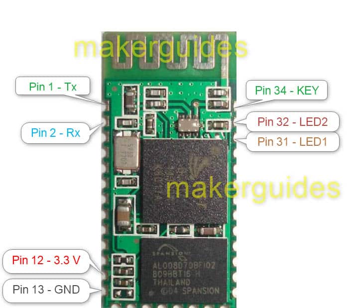
I have explained what each pin name means in the table below:
| Pin Number | Pin Name | Pin Description |
| 1 | Tx | UART data output pin ( has an internal weak pull-up option) |
| 2 | Rx | UART data input pin (has an internal weak pull-down) |
| 12 | 3.3 V | Power supply for the HC-05 module |
| 13 | GND | Ground pin. All voltages are referenced with respect to this pin |
| 31 | LED1 | GPIO output pin – use for connection indication |
| 32 | LED2 | GPIO output pin |
| 34 | KEY | GPIO input pin (used to put the HC-05 module into AT commands mode. |
What helps you most is the pin definition of the complete HC-05 Bluetooth module.

STATE pin → The STATE pin on the HC-05 Module indicates whether the module is connected.
RXD Pin → Data receive pin. You connect the ESP32 transmit pin to the RXD pin. The received data will be transmitted over Bluetooth wirelessly.
TXD Pin → Data transmit pin. Data received on Bluetooth will be transmitted out on this pin.
GND → Ground pin of the module.
VCC → Connect 5 V to this pin.
EN → You use this pin to put the HC-05 module in AT command mode. Drive this pin HIGH to put the module in command mode. By default, it will be in data mode.
HC-05 Key Features
Here are the key features of the Bluetooth module present in the HC-05 part.
| USB protocol supported | Full speed USB v1.1 complainant with USB 2.0 |
| Frequency band | 2.4 GHz ISM band |
| Frequency modulation | GFSK – Gaussian Frequency Shift Keying |
| Communication | Asynchronous at 2 Mbps (maximum) |
| Operating Voltage | 3.3 V |
| Operating temperature | -20 to +55 degrees |
| Dimension | 27 mm x 13 mm x 2 mm |
HC-05 Bluetooth Module Schematics
Here are the internal SoC HC-05 Bluetooth module schematics:
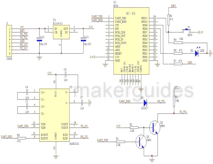
HC-05 AT Commands
For a complete list of AT commands used for the HC-05 Module please refer to this link.
Here are a few examples of using AT commands with the HC-05 Bluetooth module.
Reading the software version of the HC-05 Module
Send the following command using ESP32 UART Tx pin
at+version?\r\n
The response will be
+VERSION:2.0-20100601
OK
Get Module Bluetooth address
Send the following command to read the Bluetooth address of the HC-05 module
at+addr?\r\n
The response from the HC-05 will be similar to the below lines
+ADDR:1234:56:abcdef
OK
A few notes on AT commands:
- AT command is case-sensitive.
- AT command should always end with a line terminator ( “Enter” or “\r\n” ).
- HC-06 modules don’t need the line terminator.
- When you keep the PIN34 pin high, all AT commands can be used
Here is a list of Error codes that may come in handy when the commands fail and the HC-05 returns an error as a response. Each error has a specific code. Please refer to the table below.
| Error code (Hex) | Note |
| 0 | AT command error |
| 1 | Default result |
| 2 | PSKEY write error |
| 3 | Too long length of the device name (more than 32 bytes). |
| 4 | No device name |
| 5 | Bluetooth address: NAP is too long. |
| 6 | Bluetooth address: UAP is too long. |
| 7 | Bluetooth address: LAP is too long. |
| 8 | No PIO number’s mask |
| 9 | No PIO number |
| A | No Bluetooth devices. |
| B | Too length of devices |
| C | No inquire access code |
| D | Too long length of inquire access code |
| E | Invalid inquire access code |
| F | The length of passkey is 0. |
| 10 | Too long length of passkey (more than 16 bytes) |
| 11 | Invalid module role |
| 12 | Invalid baud rate |
| 13 | Invalid stop bit |
| 14 | Invalid parity bit |
| 15 | Authentication device is not at the pair list. |
| 16 | SPP lib hasn’t been initialized |
| 17 | SPP lib has been repeated initialization. |
| 18 | Invalid inquire mode |
| 19 | Too long inquire time |
| 1A | No Bluetooth address |
| 1B | Invalid safe mode |
Let’s connect an HC-05 Bluetooth Module to ESP32 in the next section.
Instructions To Connect The HC-05 Bluetooth Module to ESP32
I will show you how to build a project using ESP32 and the HC-05 module. Let’s get started with the hardware connections.
Step 1: Complete the hardware connections
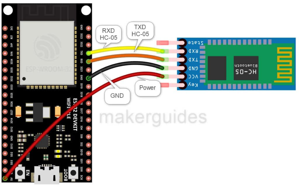
Start with the ground connections. If you have to use other pins, edit the code accordingly. Power the entire system only after completing all the connections.
ESP32 and the HC-05 Bluetooth module connection guide.
- Connect the GND pin of the HC-05 module to ESP32’s GND pin
- TXD pin of the ESP32 module goes to the RXD pin of the HC-05 module
- RXD pin of the ESP32 module goes to the TXD pin of the HC-05 module
- Connect VCC pin of the ESP32 to VCC pin of the Bluetooth module
Step 2: Program the ESP32 with the code below
Follow the next step to understand the code implementation. You can use the code below to test the ESP32 module and the connected HC-05 Bluetooth Module.
Please follow our guide to install the ESP32 core on the Arduino IDE.
// Program to test the connected HC-05 Module


void setup() {
  Serial.begin(9600); /* Set the baud rate for serial communication */
}


void loop() {
  if (Serial.available()) /* If data is available on serial port */
  {
    Serial.write(Serial.read()); /* Print character received on to the serial monitor */
  }
}
Step 3: Code Walkthrough
Code Explanation:
We test the connection to an HC-05 Bluetooth module by reading and echoing any characters from the module to the serial monitor. Here is the explanation of the program:
We don’t have to use any libraries as the code doesn’t use any special interface other than UART.
void setup() {
  Serial.begin(9600); /* Set the baud rate for serial communication */
}
This is the setup() function, called once when the ESP32 is powered on or reset. In this function, we use the Serial.begin() function to initialize serial communication with a baud rate of 9600.
void loop() {
  if (Serial.available()) /* If data is available on serial port */
  {
    Serial.write(Serial.read()); /* Print character received on to the serial monitor */
  }
}
This is the loop() function, repeated after the setup() function is executed. The Serial.available() function checks if any data is available on the serial port. If data is available, the Serial.read() function is called to read the data, and then the Serial.write() function is used to send the data back to the serial monitor.
This causes any characters received from the HC-05 Bluetooth module to be echoed back to the user via the serial monitor.
Overall, this program sets up the serial communication and continuously listens for incoming data on the serial port.
If any data is received, it is immediately echoed back to the serial monitor.
This allows you to test the connection to an HC-05 Bluetooth module and verify that data is transmitted and received correctly.
FAQs About The ESP32 And HC-05 Bluetooth Module
I have included a list of the most frequently asked questions about projects built using the ESP32 and the HC-05 Bluetooth modules.
What is the default baud rate of the HC-05 module?
The default baud rate of the HC-05 module is 9600 in data mode. In command mode, the baud rate is 38400.
What is the HC-05 Bluetooth module?
The HC-05 Bluetooth module adds wireless communication ability to other devices. It is a low-cost and easy-to-use solution. The HC-05 Bluetooth module talks to the host device over serial communication.
My number one preference is to bring Bluetooth features to Arduino projects.
How does the HC-05 module differ from the HC-06 module?
Both HC-05 and HC-06 support Bluetooth communication with smartphones. The main difference between the HC-05 and HC-06 modules is in the features. The HC-05 module supports both master and slave roles in Bluetooth communication, while the HC-06 module only supports slave mode.
How do I configure the HC-05 module?
The HC-05 module connects to ESP32 or Arduino UNO via serial pins. You can configure the HC-05 module using AT commands. To enter the AT command mode, pull the KEY pin of the module low.
Once in AT command mode, you can set the name, PIN code, baud rate, and other settings by following the commands guide.
What are some applications of the HC-05 Bluetooth module?
The HC-05 module can be used in various applications, such as remote control, wireless data transfer, and Bluetooth audio streaming. It can be used in robotics, home automation, garden watering, IoT, and many other projects requiring wireless communication.
Can the HC-05 module be used with a smartphone or tablet?
You can use the HC-05 module with a smartphone or tablet that supports Bluetooth communication. You can use a Bluetooth terminal app to send and receive data to and from the module.
How do I connect the HC-05 module to my ESP32?
The HC-05 module can be connected to an ESP32 using the serial interface using the UART pins on the ESP32 Module. You will need to connect the TX pin of the HC-05 module to the RX pin of the ESP32.
Connect the RX pin of the HC-05 module to the TX pin of the ESP32. Of course, you need to connect the power and ground pins of the module to your power supply.
Conclusion
In this article, I have covered all the essential information about the HC-05 module and how to interface with an ESP32 microcontroller.
I have given you complete information on the working of HC-05 Bluetooth, and provided a wiring diagram and example code for you to use.
If you have further questions about the Bluetooth modules, please post them in the comments section below.
I’d love to hear from you! Let us know if there’s anything else you’d like me to cover in future articles.

I am Puneeth. I love tinkering with open-source projects, Arduino, ESP32, Pi and more. I have worked with many different Arduino boards and currently I am exploring, Arduino powered LoRa, Power line communication and IoT.

jo
Friday 22nd of March 2024
Hi, How do i connect the arduino with the hc-05 to the esp32 through bluetooth? no wires.
martijn
Monday 15th of January 2024
Hello, Good tutorial, saldy my esp32 went broken so i need to retry this when the new ones come in. I dont yet understand what the code needs to do ? can u explain please so when i have my setup finished i know what will happen. Thanks greetz Martijn
Grabers Sandor
Tuesday 12th of March 2024
@Stefan Maetschke, This project is thus useless, as the ESP32 itself includes Bluetooth. It would be more useful to exchange information between the ESP32 and HC-06-equipped arduino board using Bluetooth.
Grabers
Stefan Maetschke
Monday 15th of January 2024
Hi, if you have an ESP32 you usually would not use an external Bluetooth module, since ESP32 usually has a built-in Bluetooth module. So, this article only applies if you have existing code for an Arduino that you want to transfer to an ESP32 (with minimum changes).