An RGB Color sensor helps you accurately detect an object’s color in your Arduino projects. There are a lot of applications of color sensors in industrial applications too.
Sorting the packages based on color, detecting the freshness of perishable items, detecting and correcting lighting color, and driving ambiance light based on the screen’s content, are a few example applications of TCS34725 RGB Sensors.
This article will show you all the steps needed to build an Arduino project with TCS34725 RGB Sensor.
In the following sections, I have presented a step-by-step guide to connecting the sensor to an Arduino Board (Arduino UNO).
In the later sections, you will find the example code you can use to communicate with the RGB color sensor.
Let’s get started!
Components Needed To Build Arduino And TCS34725 RGB Color Sensor Project
Hardware Components
- Arduino Uno Rev3 x 1
- RGB Color sensor – TCS34725 x 1
- Dupont wire x 3
- Arduino USB cable (for powering Arduino and programming) x 1
- Breadboard x 1
- BergStick Connectors (optional)
Software
Makerguides.com is a participant in the Amazon Services LLC Associates Program, an affiliate advertising program designed to provide a means for sites to earn advertising fees by advertising and linking to products on Amazon.com.
What Is An RGB Sensor?
RGB stands for Red, Green, and Blue. An RGB sensor can independently detect the color intensity of red, green, and blue colors. It can also measure brightness.
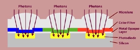
The color sensor achieves this by using an RGB color filter at its input. The red color filter allows only the red color to pass through it.
The light falls on the photodiode, whose current will vary depending on the amount of incident light.
The current will be converted to a voltage using a signal conditioner which can be read using an ADC.
Here is the block diagram of the TCS34725 sensor.
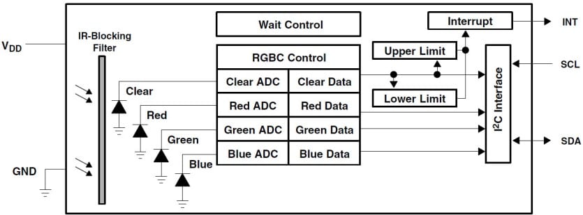
The IR block filter in the TCS34725 helps in sensing ambient light. Ambient light sensing is used in your phones when you set the brightness level to Auto.
You can also find applications in TCs and Screens whose brightness will adapt automatically to their ambient.
The TCS34725 has an I2C interface (SDA and SCL) that connects to the Arduino Board. The IC also has an optional interrupt output pin which can be used to interrupt Arduino.
An example application is a fruit sorting machine. The color will be different if a fruit is not ripened.
The Arduino can use this interrupt to trigger a solenoid to let the unripened fruit into another conveyor.
The sensor supports a sleep state where the typical current consumption is 2.5 uA.
Hence, the Color sensor TCS34725 is an excellent choice for battery-powered applications.
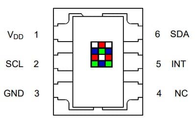
The below table gives the pin description of the color sensor IC – TCS34725.

| Pin number | Pin Name | Pin Type | Description |
| 1 | VDD | Power | Supply voltage |
| 2 | SCL | Input | I2C Clock signal |
| 3 | GND | Power | Supply ground reference |
| 4 | NC | – | Do not connect |
| 5 | INT | Output | Open drain interrupt signal |
| 6 | SDA | Input/Output | I2C Data signal |
You can find the datasheet of the TCS34725 color sensor here.
Step-By-Step Instructions To Connect A TCS34725 Color Sensor To Arduino
The following section gives step-by-step details to connect the color sensor to your Arduino board.
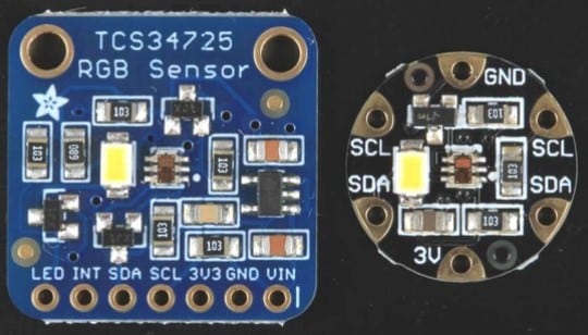
Several versions of the boards are available, as you can see from the image below.
The guide applies to all the variants of the TCS34725 RGB sensor boards.
How To Connect TCS34725 RGB Sensor With Arduino?
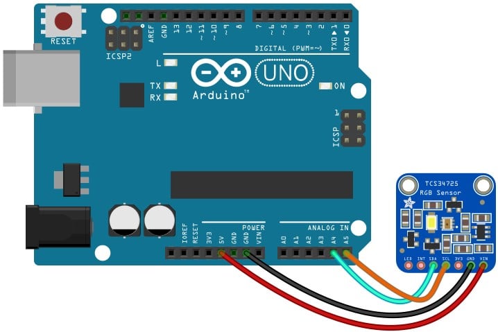
Here are the details required to complete the Arduino and the color sensor TCS34725 RGB sensor.
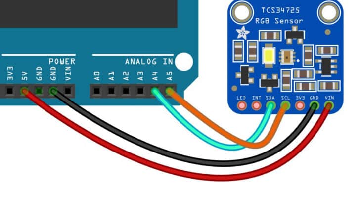
The final connection will look like the below image.
Step 1: Let us begin with the TCS34725 color sensor
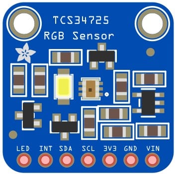
There are seven pins available on this particular module. Depending on the module you have, the number of pins may differ. Make sure that you match the pins according to the module.
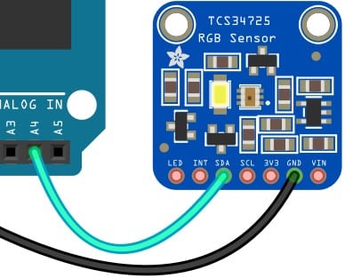
Step 2: Connect the GND pin on the color sensor module with Arduino
Connect the GND pin of the Arduino (there are many GND pins. You can choose the one which eases the connection) to the GND pin on the RGB sensor.
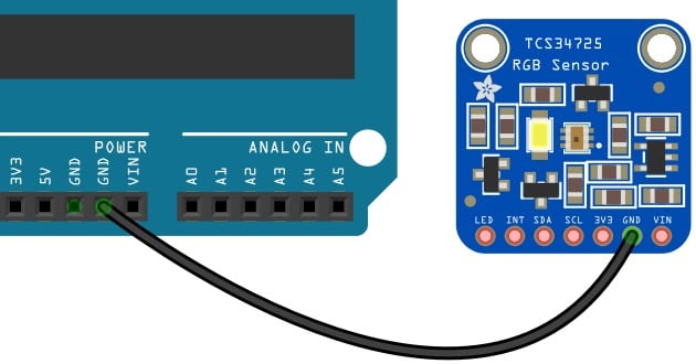
Always start with the ground connection so both boards will have a common reference before making other connections.
Step 3: Connect the I2C data line next
Connect the Pin A4 on the Arduino to the SDA pin on the color sensor IC.
Step 4: Connect the I2C Clock line
Connect the pin A5 on the Arduino to the SCL pin on the color sensor IC (orange wire in the below picture)
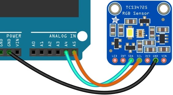
A note about I2C lines. Pins A4 and A5 on the Arduino pins have I2C as one of the functions. If the I2C is used.
You can read about the I2C pins and the supported Arduino I2C functions here.
Step 5: Connect the power pin
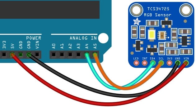
Connect the Sensor pin labelled VIN to the 5 V pin on the Arduino. The RGB color sensor module also provides 3.3 V.
You can leave the 3.3 V pin unconnected on the RGB color sensor.
Congrats! You have now completed the required connections between the Arduino and the TCS34725 RGB color sensor.
TCS34725 Library Installation And Arduino Code Examples
In this setion I will show how to install the Adafruit libary for the RGB color sensor.
The Adafruit library comes with a hsot of good examples which you can easily edit and apply to your projects.
Let’s get started!
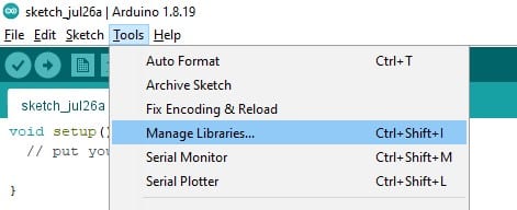
Step 1: Open Library manager
Open the Arduino IDE, Click on Tools menu. Select “Manage Library” from the options available.
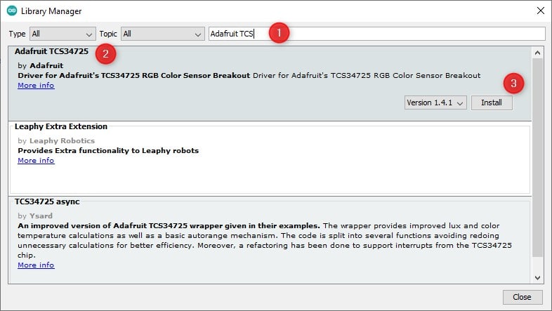
Step 2: Search for the Adafruit Library
Once you type “TCS” in the search bar, you will find a list of matching libraries available. Select the “Adafruit TCS34725” from the library options.
Click on the install button to install the Arduino Library.
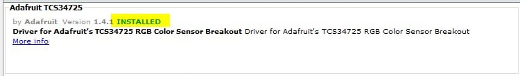
Once installed, you can see the status as “installed”, as shown in the figure below.
Step 3: Open the Adafruit example code
Congratulations on installing the Adafruit library successfully. To view the available example codes, please refer to the below image.
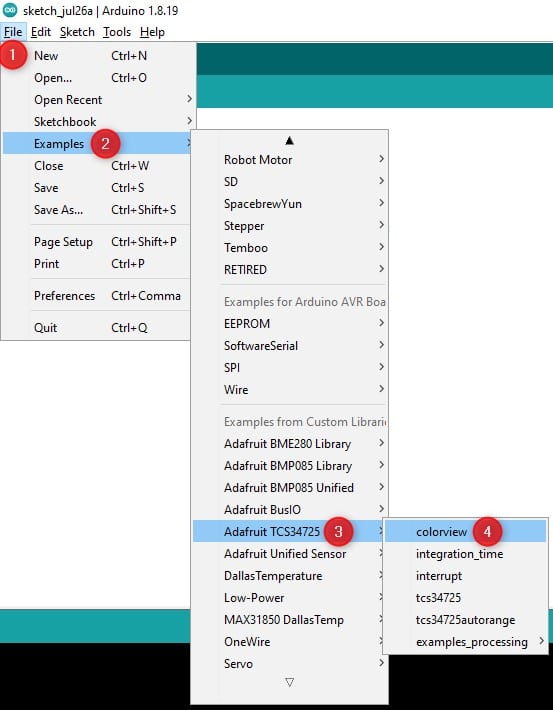
- Click on File
- Select Examples option
- Browse and locate “Adafruit TCS34725” Example
- Click on the Colorview example.
The example will open in the IDE. The code is given below.
#include "Wire.h"
#include "Adafruit_TCS34725.h"

// Pick analog outputs, for the UNO these three work well
// use ~560  ohm resistor between Red & Blue, ~1K for green (its brighter)
#define redpin 3
#define greenpin 5
#define bluepin 6
// for a common anode LED, connect the common pin to +5V
// for common cathode, connect the common to ground

// set to false if using a common cathode LED
#define commonAnode true

// our RGB -> eye-recognized gamma color
byte gammatable[256];

Adafruit_TCS34725 tcs = Adafruit_TCS34725(TCS34725_INTEGRATIONTIME_50MS, TCS34725_GAIN_4X);

void setup() {
  Serial.begin(9600);
  //Serial.println("Color View Test!");

  if (tcs.begin()) {
    //Serial.println("Found sensor");
  } else {
    Serial.println("No TCS34725 found ... check your connections");
    while (1); // halt!
  }

  // use these three pins to drive an LED
  pinMode(redpin, OUTPUT);
  pinMode(greenpin, OUTPUT);
  pinMode(bluepin, OUTPUT);

  // thanks PhilB for this gamma table!
  // it helps convert RGB colors to what humans see
  for (int i = 0; i < 256; i++) {
    float x = i;
    x /= 255;
    x = pow(x, 2.5);
    x *= 255;

    if (commonAnode) {
      gammatable[i] = 255 - x;
    } else {
      gammatable[i] = x;
    }
    //Serial.println(gammatable[i]);
  }
}

void loop() {
  float red, green, blue;
  tcs.setInterrupt(false);  // turn on LED
  delay(60);  // takes 50ms to read
  tcs.getRGB(&red, &green, &blue);
  tcs.setInterrupt(true);  // turn off LED

  Serial.print("R:\t"); Serial.print(int(red));
  Serial.print("\tG:\t"); Serial.print(int(green));
  Serial.print("\tB:\t"); Serial.print(int(blue));

  Serial.print("\n");

  analogWrite(redpin, gammatable[(int)red]);
  analogWrite(greenpin, gammatable[(int)green]);
  analogWrite(bluepin, gammatable[(int)blue]);
}
In the Colorview example, you will read the object’s color and drive an RGB LED to represent the detected color.
This example uses an additional LED that is connected to Arduino pins, as shown in the code below:
#define redpin 3
#define greenpin 5
#define bluepin 6
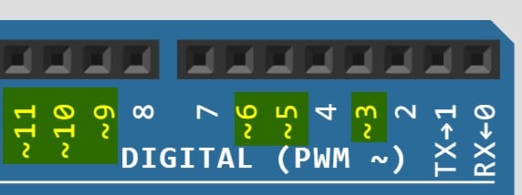
The pins 3, 5, and 6 of the Arduino UNO are PWM compatible.
You can easily find the pins on the Arduino, which are PWM compatible (heloful in driving analog values to the LEDs for varying brightness) by looking at the “~” symbol before the pin label.
I have shown an example here:
The below line initializes the object to handle the color sensor functions.
Adafruit_TCS34725 tcs = Adafruit_TCS34725(TCS34725_INTEGRATIONTIME_50MS, TCS34725_GAIN_4X);
You can read the RGB color values at every fixed interval using the getRGB method, as shown in the code line below.
tcs.getRGB(&red, &green, &blue);
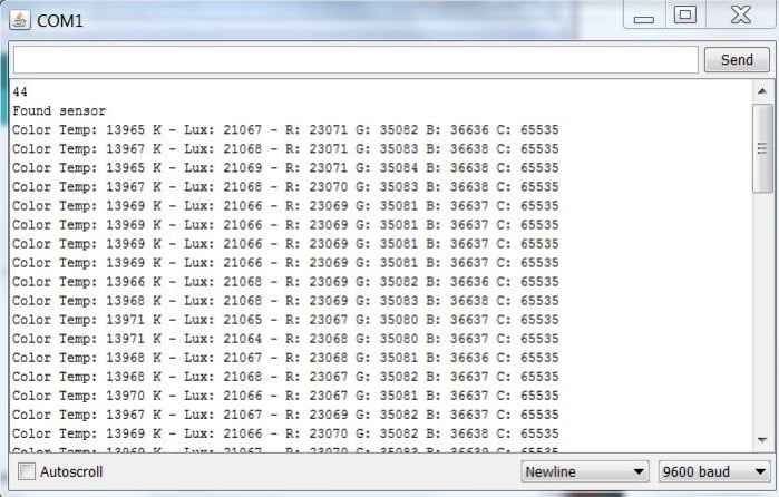
Once you have the RGB values, you can post the color information on a screen or a terminal or drive the LED with the same color.
The terminal window will have data similar to the image shown below.
We are recreating the color of the object using an RGB LED. The below lines will drive the LED to match the detected color.
  analogWrite(redpin, gammatable[(int)red]);
  analogWrite(greenpin, gammatable[(int)green]);
  analogWrite(bluepin, gammatable[(int)blue]);
You can convert this code into a worthwhile project by adding your logic.
If you have any questions, you can always drop a comment in the comment section.
FAQ’s About The Arduino RGB Color Sensor TCS34725
In this section, you will get answers to the most frequent questions on the TCS34275 RGB color sensor.
If your question is still not answered, please post the question in the comment section.
1) What are the applications of RGB sensors?
The applications of RGB color sensors are
- RGB LED backlight control
- Measuring color temperature of ambient light
- Measuring ambiance light for automatic display control
- Analyzing fluid and gas
- Product color verification and sorting
- Industrial automation and many more
2) How does a RGB color sensor work?
An RGB color sensor detects the amount of Red, Green, and Blue light components in the light.
The sensor will have three color filters to separate the R, G, and B components.
For more information, refer to this article’s RGB sensor basics section.
3) How do you connect Arduino to the RGB Color sensor?
You can use the I2C interface to connect Arduino to the RGB color sensor TCS34275.
Depending on the sensor type, you may have to use UART, I2C, or SPI interface.
In the article, you can see how a TCS34275 is connected to an Arduino using I2C lines.
4) Can Arduino detect colors?
Arduino can detect colors when you use a color sensor along with it.
TCS34275 is an RGB color sensor that lets you quickly see objects’ colors.
The connection details, example code, and working principle of an RGB sensor are explained in the sections above.
5) How many colors can an RGB sensor detect?
The RGB color sensors detect the amount of Red, Green, and Blue colors.
Since the three colors can be used with different proportions to create many colors, RGB sensors too can detect several colors.
With an 8-bit RGB color sensor, the red, green, and blue colors can take any values from 0 to 255.
It means, in total, we can have 256 * 256 * 256 = ~16 million colors!
Hence, you can use color sensors to detect a vivid range of colors in your next color detection project.
Conclusion
I have taken you through all the critical information needed to build an Arduino color sensor project in this article.
I believe the article was beneficial and easy to understand.
I have used the RGB color sensor for a few demo projects where the goal was to detect the color of the fruit to determine whether the fruit is wholly ripened or not.
The Arduino used the color sensor data to predict the fruits’ shelf life.
I would love to know the projects you will build using the Arduino color sensor.
Please provide a link to the projects which you create next. I will be excited to see your projects in action.
Did you have any challenges building your projects or any lessons learned? Please share it with us as well in the comments section!
If you have found this article helpful, don’t forget to share it with your friends.
You can share your feedback on the article with us to help us improve the articles in the future.
Please let us know about the next Arduino project you would love to read!

I am Puneeth. I love tinkering with open-source projects, Arduino, ESP32, Pi and more. I have worked with many different Arduino boards and currently I am exploring, Arduino powered LoRa, Power line communication and IoT.
Erfan
Thursday 28th of March 2024
Hello Do not be tired I want to use this sensor to distinguish between silver color and white color, but the sensor gives the same number to both colors, like 174. How can I increase the accuracy of this sensor?
Erfan
Friday 29th of March 2024
@Erfan, 🙏🤌❤️❤️
Erfan
Friday 29th of March 2024
@Stefan Maetschke, Hello sorry I don't understand what you mean, can you say it more simply? If you can send a message to this address in Telegram, thank you @erfan214358552311
Stefan Maetschke
Thursday 28th of March 2024
Hi, you could try to illuminate the objects (silver vs white) color with an RGB LED and find an RGB color where the color sensor reacts differently to the two colors (white, silver). Instead of illuminating with different colors you could also try different color filters (colored foils) in front of the sensor. Lastly, maybe the silver color is more reflective than the white color and a photoreceptive sensor (brightness sensor) can detect the difference.