One of the basic HMI (Human Machine Interface) is an Encoder. With just one encoder, you can handle multiple menus and navigate back and forth through the list displayed on the LCD.
The rotary encoder is very easy to learn and understand. It doesn’t need additional power or complex software to decode the position.
Since it is a 360-degree encoder, the user interaction will be seamless.
In this article, I will share with you all the details needed to understand the rotary encoder.
I will provide you with the basic working principle of a quadrature rotary encoder and step-by-step instructions to connect it to an Arduino board.
You will also get example code for you to use in your own Arduino and quadrature rotary encoder project.
Let’s begin!
Components Needed To Build Arduino And Quadrature Rotary Encoder Project
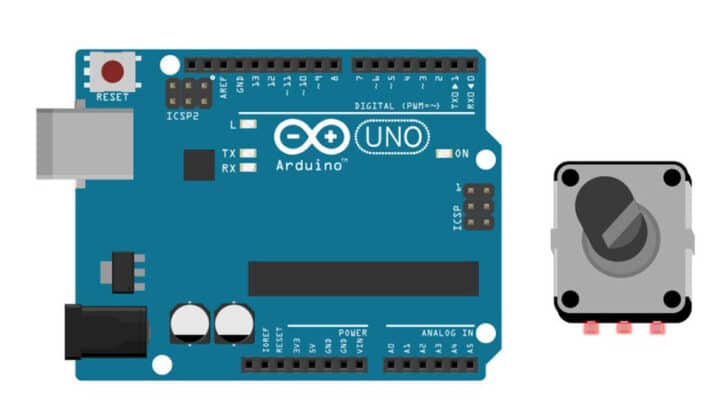
Hardware Components
- Arduino Uno Rev3 x 1
- Quadrature Encoder x 1
- Dupont wire x 3
- Arduino USB cable (for powering Arduino and programming) x 1
- Breadboard x 1
Software
Makerguides.com is a participant in the Amazon Services LLC Associates Program, an affiliate advertising program designed to provide a means for sites to earn advertising fees by advertising and linking to products on Amazon.com.
What Is A Quadrature Rotary Encoder?
Rotary encoders convert angular motion into equivalent digital signals. You can find the encoders in various applications such as HMI boards, cameras, multimedia volume, channel tuners, and much more.
You will come across various encoders, such as linear, incremental, and absolute.
The Quadrature encoder, which we are using in this article, produces digital signals that must be processed using software on the Arduino.
In the coming sections, I will explain the principle of working of a quadrature encoder along with the waveforms.
By the end of this section, you will be confident in building your software to detect both the direction of rotation and the number of steps.
Let’s dive into the basics!
Pinouts Of A Quadrature Rotary Encoder
The quadrature rotary encoder produces rectangular waves when you turn the knob. There are three essential signals/Pins present.
In the table below, you can find the commonly used pin terminology and the description.
| Pin number | Pin Label | Pin definition |
| 1 | A / DT | Quadrature output pin A |
| 2 | B / CLK | Quadrature Output pin B |
| 3 | C | Common pin |
| 4 | SW | Push Switch output |
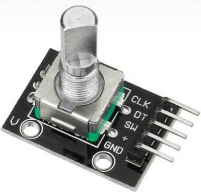
In some quadrature encoders, OUTPUT A and OUTPUT B have alternate names DT (Data) and CLK (Clock).
So you know how to handle encoders with different names, such as the one in the image below.
Understanding Output Signals Of A Quadrature Rotary Encoder
I will share the basics of the encoder’s digital signal interpretation and examples. For the discussion, I am using a part from Bourns.
The part number of the encoder is PEC11L-4120F-S0020. You can find the datasheet of the part from the link here.
The encoder can either turn in the clockwise or the anticlockwise direction.
Depending on the direction of rotation, the digital Signal on Pin A or the digital Signal on Pin B will lead the output.
Here is a picture depicting the relationship between the direction of rotation and the digital signals on A and B
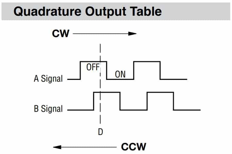
When you turn the knob in the clockwise (CW) direction, The signal on A changes first, followed by signal B.
If you turn the encoder in the counterclockwise direction (CCW), Signal B will change first, followed by Signal A.
The order of signal arrival on the MCU port pins is critical in understanding and implementing the software logic.
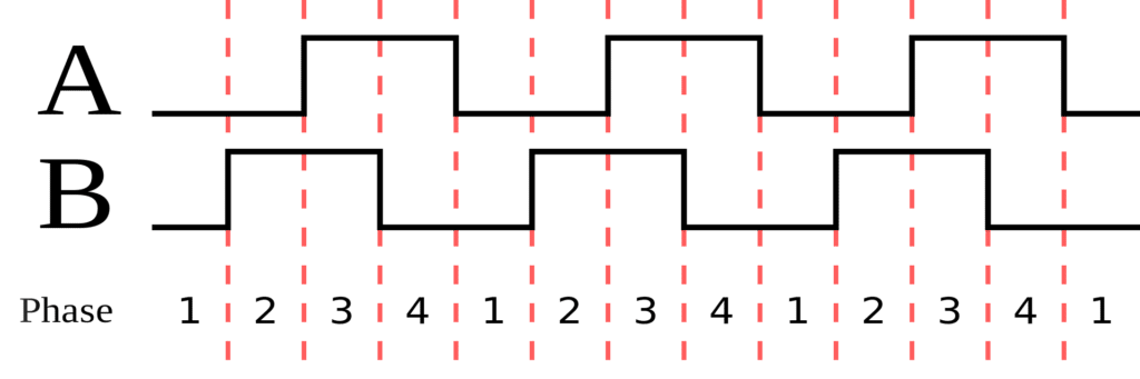
In the above image, you can see four phases corresponding to the digital signal levels on pins A and B. The order of these phases depends on the direction of rotation.
They can be either 4-3-2-1 or 1-2-3-4, depending on whether you turn the encoder CW or in the CCW direction.
If you are using a readymade board with an Encoder mounted on it, you dont have to do anything else towards completing the encoder circuit.
In the next section, you will see what electric circuit you should build around the encoder digital signal pins to make the circuit work.
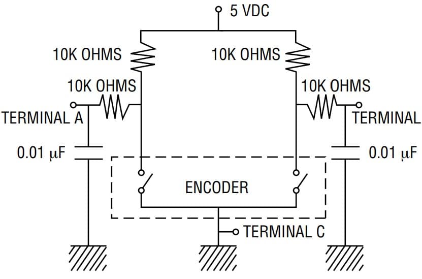
The encoder is only a tiny part represented by the dotted line in the complete circuit. Terminal C is often directly connected to the ground. The signals A and B are connected to 5 V via ten kΩ resistors.
These are called pull-up resistors. These resistors help the signal to reach 5 V to represent Logic 1.
The capacitors are optional but help filter switching and debounce noise from the encoder.
Understanding Encoder Parameters
The number of detents – Every time you turn an encoder by a slight angle, you will feel a ‘tick.’ The tick marks the stable position of the encoder.
It also gives good feedback to the user working with your project.
There can be ten detents for a 360-degree rotation of an encoder. The number of detents will vary from 6 to 60. Refer to the part’s datasheet for the correct number of detents.
Switch – Some encoders come with a built-in switch. This is a handy feature. The user can use this switch to confirm their selection in the menu!
Debounce noise – The encoder is an electro-mechanical part. Since the A and B signals are generated using two switches in the encoder, you will encounter the switching noise.
The datasheet will typically mention the duration of the noise.
The software algorithm should have to debounce the logic implemented to ensure the noise is filtered completely.
Step-By-Step Instructions To Connect A Quadrature Encoder To An Arduino
I will show you how to connect the rotary encoder in the Arduino in the following section. The rotary conenction is easy to do.
Lets’s start!
How To Connect Rotary Encoder To Arduino
Here are the connection details necessary to complete the Arduino and the Quadrature rotary encoder
Step 1: Start with the Encoder
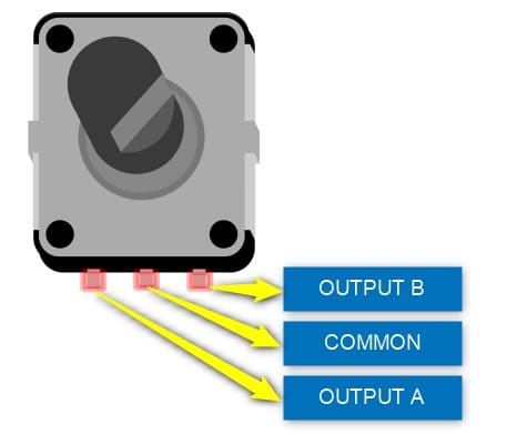
The three basic connections needed are OUTPUT A, B, and COMMON. If you are using a readymade boards, you will additionally have to connect a 5 V line as well. Let us get started.
Step 2: Make the Ground connection first
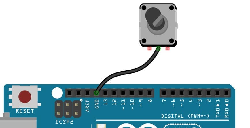
Connect any of the GND pin of the Arduino to the Common pin of the Encoder.
I always recommend to start with the GND connection first.
Step 3: Connect the OUTPUT A Pin
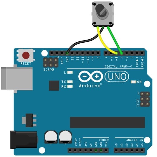
Connect the Encoder pin labeled “OUTPUT A” or “DT” to the Arduino Pin 4. You can choose any of the digital input pins.
Using the encoder without the board, you should enable internal pullups for both GPIOs. The pull-ups are a must.
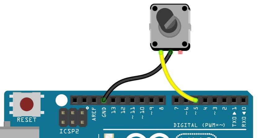
Step 4: Connect the OUTPUT B Pin
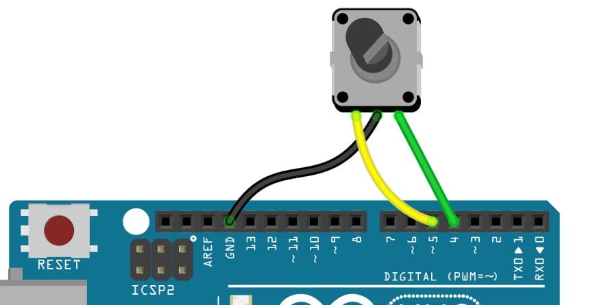
Connect the pin labeled “CLK” or SIGNAL B” to the Arduino Pin 5. You must enable the internal pull-up for the Arduino Pin 5.
If you are using a board such as KY040, you dont need to use internal pull-ups as the board already has the required pull-ups externally.
The final connection will look like the image shown below
If you dont like to use the built-in pull-ups or if you need to have debounce filters as well, you can construct them in the way shown below.
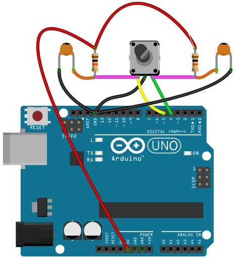
I have used resistors of value ten kΩ. You can use the 0.1 nF capacitors. You can also modify your code to drive two LEDs.
Optionally, you can use the LEDs to indicate the direction of rotation (Clockwise or Counterclockwise).
Congrats! The connections are now complete.
Arduino Code For Quadrature Rotary Encoder project
Here is the working code for a quadrature type rotary encoder connected to Arduino pins 4 and 5. The code attribution is retained in the comments.
 // Rotary Encoder Inputs
 #define inputCLK 4
 #define inputDT 5

 // LED Outputs
 #define ledCW 8
 #define ledCCW 9

 int counter = 0;
 int currentStateCLK;
 int previousStateCLK;

 String encdir ="";

 void setup() {
   // Set encoder pins as inputs
   pinMode (inputCLK,INPUT);
   pinMode (inputDT,INPUT);

   // Set LED pins as outputs
   pinMode (ledCW,OUTPUT);
   pinMode (ledCCW,OUTPUT);

   // Setup Serial Monitor
   Serial.begin (9600);

   // Read the initial state of inputCLK
   // Assign to previousStateCLK variable
   previousStateCLK = digitalRead(inputCLK);

 }

 void loop() {
  // Read the current state of inputCLK
   currentStateCLK = digitalRead(inputCLK);

   // If the previous and the current state of the inputCLK are different then a pulse has occurred
   if (currentStateCLK != previousStateCLK){

     // If the inputDT state is different than the inputCLK state then
     // the encoder is rotating counterclockwise
     if (digitalRead(inputDT) != currentStateCLK) {
       counter--;
       encdir ="CCW";
       digitalWrite(ledCW, LOW);
       digitalWrite(ledCCW, HIGH);

     } else {
       // Encoder is rotating clockwise
       counter++;
       encdir ="CW";
       digitalWrite(ledCW, HIGH);
       digitalWrite(ledCCW, LOW);

     }
     Serial.print("Direction: ");
     Serial.print(encdir);
     Serial.print(" -- Value: ");
     Serial.println(counter);
   }
   // Update previousStateCLK with the current state
   previousStateCLK = currentStateCLK;
 }
Let us go through the key sections of the code to understand the logic.
#define inputCLK 4
#define inputDT 5
You are defining the GPIOs which are connected to the encoder. You can change the pins if you have connected the encoder to some other pins.
Make sure you match the pins connected to the hardware to the sketch-defined pins.
 #define ledCW 8
 #define ledCCW 9
The above two lines of code are optional. If you want to debug your code, it will provide easier access. You can use a multimeter or just connect an LED to these pins.
Take care of limiting current through the LED (220 ohms or 470 ohms). The above part is optional.
pinMode (inputCLK,INPUT);
pinMode (inputDT,INPUT);
In the above lines, you declare two variable input pins as inputs. If you are not using external pullups for Signal A and Signal B, then you can use below two lines instead of the above lines.
pinMode (inputCLK,INPUT_PULLUP);
pinMode (inputDT,INPUT_PULLUP);
The code below defines variables to hold the status of the counter and the CLK pin. These help detect the edge transitions on the encoder pins simply.
 int counter = 0;
 int currentStateCLK;
 int previousStateCLK;
Next comes the loop() function where the heart of the logic is implemented. We check the CLK input and compare it to the previousStateCLK value. If it has changed, then a pulse has occurred.
You will now monitor the status of the CLK input and continuously compare it with its previous value.
If the current status is different from the prior status, it means there was a rotation, and the edge transition has occurred,
In the next section, you will identify the encoder rotation’s direction. Based on the status of the DT pin and the CLK pin, you will decide the direction of the rotation.
Further, you can decide to drive LEDs or print custom messages on the terminal to display the direction of rotation and the counter value.
FAQ’s About The Rotary Quadrature Encoder And Arduino Project
I have compiled the answers to the most frequently asked questions on the Rotary encoder-related projects.
If your question is not answered here, please drop a comment in the comment section.
1) How do I use a rotary encoder with Arduino?
You can easily use a rotary encoder with an Arduino. You will require only two GPIOs to detect the direction of rotation and the counts.
You can refer to the sections above for the step-by-step guide to learn connecting a rotary encoder to the Arduino.
2) What does a rotary encoder do?
A rotary encoder converts the rotational motion given by the user to digital signals, which an Arduino can process. There are several types of rotary encoders.
Some encoders provide the precise position of the rotation while the others provide relative movement.
The quadrature encoders allow you to turn them beyond 360 degrees. You have to choose an encoder that is more suitable for your application.
3) What does the rotary encoder provide as outputs?
Rotary encoder provides two signals as output. The Signal A and Signal B are two digital signals which represent the direction of rotation.
Some encoders will have a built-in switch. You can process these signals using any of the three GPIOs.
Conclusion
In this article, I have introduced you to the quadrature rotary encoder principles along with the connections ended to build your own project.
I hope you have found all the basic details needed to comprehend and build exciting projects including the encoder soon.
I will be glad to hear about your feedback on this article. Your honest feedback will help me to bring more useful articles in the style you like.

I am Puneeth. I love tinkering with open-source projects, Arduino, ESP32, Pi and more. I have worked with many different Arduino boards and currently I am exploring, Arduino powered LoRa, Power line communication and IoT.