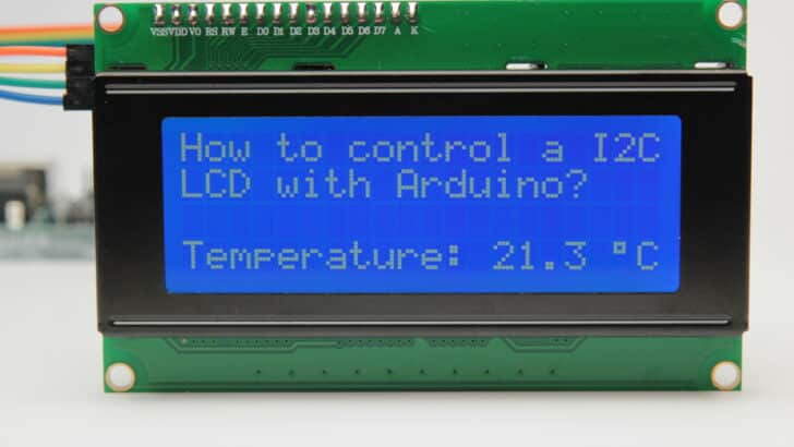
This article includes everything you need to know about using a character I2C LCD with Arduino. I have included a wiring diagram and many example codes to help you get started.
The first part of this article covers the basics of displaying text and numbers. In the second half, I will go into more detail on how to display custom characters and how you can use the other functions of the LiquidCrystal_I2C library.
Once you know how to display text and numbers on the LCD, I suggest you take a look at the articles below. In these tutorials, you will learn how to measure and display sensor data on the LCD.
Recommended articles
- How to use an HC-SR04 Ultrasonic Distance Sensor with Arduino
- How to use DHT11 and DHT22 Sensors with Arduino
- LM35 analog temperature sensor with Arduino tutorial
- TMP36 analog temperature sensor with Arduino tutorial
(I also have an article on How To Control A Character I2C LCD with ESP32 if you want to work with an ESP32 microcontroller instead).
Supplies
Hardware components
| 16×2 character I2C LCD | × 1 | Amazon | |
 | 20×4 character I2C LCD (alternative) | × 1 | Amazon |
| Arduino Uno Rev3 | × 1 | Amazon | |
| Jumper wires (male to female) | × 4 | Amazon | |
| USB cable type A/B | × 1 | Amazon |
Tools
Software
Makerguides.com is a participant in the Amazon Services LLC Associates Program, an affiliate advertising program designed to provide a means for sites to earn advertising fees by advertising and linking to products on Amazon.com. As an Amazon Associate we earn from qualifying purchases.
I2C LCD Basics
This guide is part of our hub of articles on Arduino Displays. This type of LCD is ideal for displaying text and numbers, hence the name ‘character LCD’.
The I2C LCD that we are using in this tutorial comes with a small add-on circuit mounted on the back of the module. This module features a PCF8574 chip (for I2C communication) and a potentiometer to adjust the LED backlight.
The advantage of an I2C LCD is that the wiring is very simple. You only need two data pins to control the LCD. Standard LCDs typically require around 12 connections, which can be a problem if you do not have many GPIO pins available.
Luckily, you can also buy the I2C add-on circuit separately on Amazon, so you can easily upgrade a standard LCD as well.
For a tutorial and wiring diagram for standard character LCDs, please see the following article:
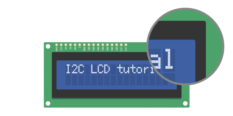
If you look closely at the LCD, you can see the small rectangles that form the individual characters of the LCD. Each rectangle is made up of a grid of 5×8 pixels. Later in this tutorial, I will show you how you can control the individual pixels to display custom characters on the LCD.
Specifications
The specifications of the 16×2, 20×4, and other sized LCDs are mostly the same. They all use the same HD44780 Hitachi LCD controller, so you can easily swap them. You will only need to change the size specifications in your Arduino code.
The specifications of a typical 16×2 I2C display can be found in the table below.
16×2 I2C LCD Specifications
| Operating voltage | 5 V |
| Controller | Hitachi HD44780 LCD controller |
| Default address | 0x27 |
| Screen resolution | 2-lines × 16 characters |
| Character resolution | 5 × 8 pixels |
| Module dimensions | 80 × 36 × 12 mm |
| Viewing area dimensions | 64.5 × 16.4 mm |
| Cost | Check price |
For more information, you can check out the datasheets below.
The 16×2 and 20×4 datasheets include the dimensions of the LCD and you can find more information about the Hitachi LCD driver in the HD44780 datasheet.
The PCF8574 chip is used in the I2C module on the back of the LCD.
How to connect the I2C LCD to Arduino UNO
The wiring diagram below shows you how to connect the I2C LCD to the Arduino. Wiring an I2C LCD is a lot easier than connecting a standard LCD. You only need to connect 4 pins instead of 12.

The connections are also given in the table below.
I2C LCD Connections
| I2C Character LCD | Arduino |
|---|---|
| GND | GND |
| VCC | 5 V |
| SDA | A4 |
| SCL | A5 |
If you are not using an Arduino Uno, the SDA and SCL pins can be at a different location.
Note that an Arduino Uno with the R3 layout (1.0 pinout) also has the SDA (data line) and SCL (clock line) pin headers close to the AREF pin. Check the table below for more details.
| Board | SDA | SCL |
|---|---|---|
| Arduino Uno | A4 | A5 |
| Arduino Nano | A4 | A5 |
| Arduino Micro | 2 | 3 |
| Arduino Mega 2560 | 20 | 21 |
| Arduino Leonardo | 2 | 3 |
| Arduino Due | 20 | 21 |
Adjusting the contrast of the LCD
After you have wired up the LCD, you will need to adjust the contrast of the display. On the I2C module, you will find a potentiometer that you can turn with a small screwdriver.
Plug in the USB connector of the Arduino to power the LCD. You should see the backlight light up. Now rotate the potentiometer until one (16×2 LCD) or 2 rows (20×4 LCD) of rectangles appear. You can tweak the contrast later if needed.
Once that is done, we can start programming the LCD.
Installing the LiquidCrystal_I2C Arduino library
In this tutorial, I will be using the LiquidCrystal_I2C library. This library has many built-in functions that make programming the LCD quite easy.
The latest version of this library can be found here on GitHub or click the download button below.
Make sure that you have this exact library installed and delete any other libraries that have the same name (LiquidCrystal_I2C). Other libraries will probably work as well but might use slightly different names for the different functions.
The LiquidCrystal_I2C library works in combination with the Wire.h library which allows you to communicate with I2C devices. This library comes pre-installed with the Arduino IDE.
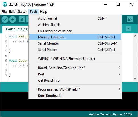
To install this library, go to Tools > Manage Libraries (Ctrl + Shift + I on Windows) in the Arduino IDE. The Library Manager will open and update the list of installed libraries.
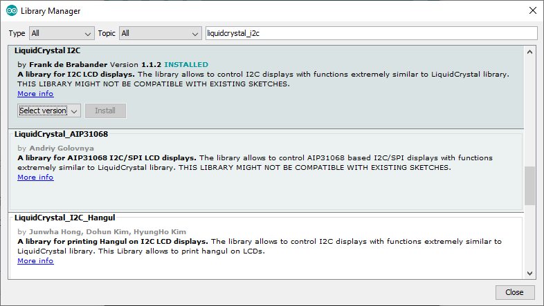
Now search for ‘liquidcrystal_i2c’ and look for the library by Frank de Brabander. Select the latest version and then click Install.
The library does include some examples that you can use, but you will have to modify them to match your hardware setup. I have included many example codes below that you can use with the wiring setup I have shown earlier.
First I will show you some basic example code and then I will explain the functions in more detail.
How to find the I2C address of my LCD?
Most I2C LCDs ship with the default address ‘0x27’, but it can be different depending on the batch/manufacturer. If this is the case, you will need to find the actual address of the LCD before you can start using it. On the Arduino website, you can find a simple example sketch that scans the I2C-bus for devices. If a device is found, it will display the address in the serial monitor.
/*I2C_scanner
  This sketch tests standard 7-bit addresses.
  Devices with higher bit address might not be seen properly.
*/

#include "Wire.h"

void setup() {
  Wire.begin();

  Serial.begin(9600);
  while (!Serial);
  Serial.println("\nI2C Scanner");
}

void loop() {
  byte error, address;
  int nDevices;

  Serial.println("Scanning...");

  nDevices = 0;
  for (address = 1; address < 127; address++ ) {
    Wire.beginTransmission(address);
    error = Wire.endTransmission();

    if (error == 0) {
      Serial.print("I2C device found at address 0x");
      if (address < 16)
        Serial.print("0");
      Serial.print(address, HEX);
      Serial.println("  !");

      nDevices++;
    }
    else if (error == 4) {
      Serial.print("Unknown error at address 0x");
      if (address < 16)
        Serial.print("0");
      Serial.println(address, HEX);
    }
  }
  if (nDevices == 0)
    Serial.println("No I2C devices found\n");
  else
    Serial.println("done\n");

  delay(5000);
}
If you upload this sketch to the Arduino and run it, you should see the following output in the Serial Monitor (Ctrl + Shift + M).
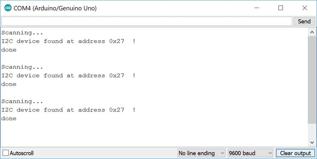
Write down the address you find, you will need it later when programming the LCD.
Basic Arduino example code for I2C LCD
You can upload the following example code to the Arduino using the Arduino IDE.
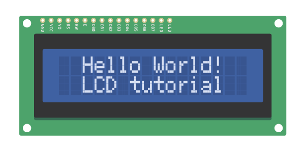
For this tutorial, I used this 16×2 I2C character LCD display, but you can use other I2C LCDs of different sizes as well. This example sketch will display the classic ‘Hello World!’ on the first line of the LCD and ‘LCD tutorial’ on the second line.
Next, I will explain how the code works.
/* I2C LCD with Arduino example code. More info: https://www.makerguides.com */

#include "Wire.h" // Library for I2C communication
#include "LiquidCrystal_I2C.h" // Library for LCD

// Wiring: SDA pin is connected to A4 and SCL pin to A5.
// Connect to LCD via I2C, default address 0x27 (A0-A2 not jumpered)
LiquidCrystal_I2C lcd = LiquidCrystal_I2C(0x27, 16, 2); // Change to (0x27,20,4) for 20x4 LCD.

void setup() {
  // Initiate the LCD:
  lcd.init();
  lcd.backlight();
}

void loop() {
  // Print 'Hello World!' on the first line of the LCD:
  lcd.setCursor(2, 0); // Set the cursor on the third column and first row.
  lcd.print("Hello World!"); // Print the string "Hello World!"
  lcd.setCursor(2, 1); //Set the cursor on the third column and the second row (counting starts at 0!).
  lcd.print("LCD tutorial");
}
You should see the following output on the LCD:
How the code works
First, the required libraries are included. As mentioned earlier we need both the Wire.h and the LiquidCrystal_I2C library. In the rest of this tutorial, I will cover more of the built-in functions of this library.
*When using the latest version of the LiquidCrystal_I2C library it is no longer needed to include the wire.h library in your sketch. The other library imports wire.h automatically.
#include "Wire.h" // Library for I2C communication
#include "LiquidCrystal_I2C.h" // Library for LCD
The next step is to create an LCD object with the LiquidCrystal_I2C class and specify the address and dimensions. For this, we use the function LiquidCrystal_I2C(address, columns, rows).
This is where you will need to change the default address to the address you found earlier if it happens to be different. When using a 20×4 LCD, change this line to LiquidCrystal_I2C(0x27,20,4);
Note that we have called the display ‘lcd’. You can give it a different name if you want like ‘menu_display’. You will need to change ‘lcd’ to the new name in the rest of the sketch.
// Connect to LCD via I2C, default address 0x27 (A0-A2 not jumpered)
LiquidCrystal_I2C lcd = LiquidCrystal_I2C(0x27, 16, 2); // Change to (0x27,20,4) for 20x4 LCD.
Setup
In the setup, the LCD is initiated with lcd.init() and the backlight is turned on with lcd.backlight().
void setup() {
  // Initiate the LCD:
  lcd.init();
  lcd.backlight();
}
Loop
In the loop section of the code, the cursor is set to the third column and the first row of the LCD with lcd.setCursor(2,0).
Note that counting starts at 0 and the first argument specifies the column. So lcd.setCursor(2,1) sets the cursor on the third column and the second row.
Next the string ‘Hello World!’ is printed with lcd.print("Hello World!"). Note that you need to place quotation marks (” “) around the text since we are printing a text string.
When you want to print numbers, no quotation marks are necessary. For example lcd.print(12345).
void loop() {
  lcd.setCursor(2, 0); // Set the cursor on the third column and first row.
  lcd.print("Hello World!"); // Print the string "Hello World!".
  lcd.setCursor(2, 1); //Set the cursor on the third column and the second row.
  lcd.print("LCD tutorial"); // Print the string "LCD tutorial".
}
If you want to see an example for displaying (changing) variables on the LCD, check out my tutorial for the HC-SR04 ultrasonic distance sensor:
Other useful functions of the LiquidCrystal_I2C library
The example sketch above shows you the basics of displaying text on the LCD. Now we will take a look at the other functions of the LiquidCrystal_I2C library.
clear()
Clears the LCD screen and positions the cursor in the upper-left corner (first row and first column) of the display. You can use this function to display different words in a loop.
#include "LiquidCrystal_I2C.h"

LiquidCrystal_I2C lcd(0x27, 16, 2);

void setup() {
  lcd.init();
  lcd.backlight();
}

void loop() {
  lcd.clear();
  lcd.print("Monday");
  delay(2000);
  lcd.clear();
  lcd.print("13:45");
  delay(2000);
}
home()
Positions the cursor in the top-left corner of the LCD. Use clear() if you also want to clear the display.
cursor()
Displays the LCD cursor: an underscore (line) at the position of the next character to be printed.
noCursor()
Hides the LCD cursor. The following example creates a blinking cursor at the end of “Hello World!”.
#include "LiquidCrystal_I2C.h"

LiquidCrystal_I2C lcd(0x27, 16, 2);

void setup() {
  lcd.init();
  lcd.backlight();
  lcd.print("Hello World!");
}

void loop() {
  lcd.cursor();
  delay(500);
  lcd.noCursor();
  delay(500);
}
blink()
Creates a blinking block style LCD cursor: a blinking rectangle at the position of the next character to be printed.
noBlink()
Disables the block style LCD cursor. The following example displays the blinking cursor for 5 seconds and then disables it for 2 seconds.
#include "LiquidCrystal_I2C.h"

LiquidCrystal_I2C lcd = LiquidCrystal_I2C(0x27, 16, 2);

void setup() {
  lcd.init();
  lcd.backlight();
  lcd.print("blink() example");
}

void loop() {
  lcd.blink();
  delay(5000);
  lcd.noBlink();
  delay(2000);
}
display()
This function turns on the LCD screen and displays any text or cursors that have been printed to the display.
noDisplay()
This function turns off any text or cursors printed to the LCD. The text/data is not cleared from the LCD memory.
This means it will be shown again when the function display() is called.
The following example creates a blinking text effect.
#include "LiquidCrystal_I2C.h"

LiquidCrystal_I2C lcd = LiquidCrystal_I2C(0x27, 16, 2);

void setup() {
  lcd.init();
  lcd.backlight();
  lcd.print("Blinking text");
}

void loop() {
  lcd.display();
  delay(2000);
  lcd.noDisplay();
  delay(2000);
}
write()
This function can be used to write a character to the LCD. See the section about creating and displaying custom characters below for more info.
scrollDisplayLeft()
Scrolls the contents of the display (text and cursor) one space to the left.
You can use this function in the loop section of the code in combination with delay(500), to create a scrolling text animation.
#include "LiquidCrystal_I2C.h"

LiquidCrystal_I2C lcd = LiquidCrystal_I2C(0x27, 16, 2);

void setup() {
  lcd.init();
  lcd.backlight();
  lcd.print("Hello World!");
}

void loop() {
  lcd.scrollDisplayLeft();
  delay(500);
}
scrollDisplayRight()
Scrolls the contents of the display (text and cursor) one space to the right.
autoscroll()
This function turns on automatic scrolling of the LCD. This causes each character output to the display to push previous characters over by one space.
If the current text direction is left-to-right (the default), the display scrolls to the left, if the current direction is right-to-left, the display scrolls to the right.
This has the effect of outputting each new character to the same location on the LCD.
The following example sketch enables automatic scrolling and prints the character 0 to 9 at the position (16,0) of the LCD. Change this to (20,0) for a 20×4 LCD.
#include "LiquidCrystal_I2C.h"

LiquidCrystal_I2C lcd = LiquidCrystal_I2C(0x27, 16, 2);

void setup() {
  lcd.init();
  lcd.backlight();
}

void loop() {
  lcd.autoscroll();
  lcd.setCursor(16, 0);
  for (int x = 0; x < 10; x++) {
    lcd.print(x);
    delay(500);
  }
  lcd.clear();
}
noAutoscroll()
Turns off automatic scrolling of the LCD.
leftToRight()
This function causes text to flow to the right from the cursor, as if the display is left-justified (default).
rightToLeft()
This function causes text to flow to the left from the cursor, as if the display is right-justified.
How to create and display custom characters?
With the function createChar() it is possible to create and display custom characters on the LCD. This is especially useful if you want to display a character that is not part of the standard ASCII character set.
CGROM and CGRAM
LCDs that are based on the Hitachi HD44780 LCD controller have two types of memory: CGROM and CGRAM (Character Generator ROM and RAM).
CGROM generates all the 5 x 8 dot character patterns from the standard 8-bit character codes. CGRAM can generate user-defined character patterns.
For 5 x 8 dot displays, CGRAM can write up to 8 custom characters and for 5 x 10 dot displays 4. For more info see the datasheet.
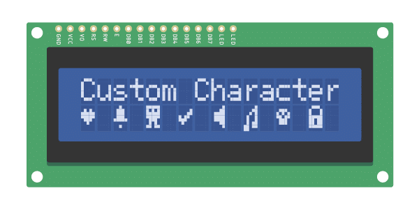
Custom character example code
The following example sketch creates and displays eight custom characters (numbered 0 – 7). You can copy the code by clicking on the button in the top right corner of the code field.
/* Arduino example code to display custom characters on I2C character LCD. More info: www.www.makerguides.com */

// Include the library:
#include "LiquidCrystal_I2C.h"

// Create lcd object of class LiquidCrystal_I2C:
LiquidCrystal_I2C lcd = LiquidCrystal_I2C(0x27, 16, 2); // Change to (0x27,20,4) for 20x4 LCD.

// Make custom characters:
byte Heart[] = {
  B00000,
  B01010,
  B11111,
  B11111,
  B01110,
  B00100,
  B00000,
  B00000
};

byte Bell[] = {
  B00100,
  B01110,
  B01110,
  B01110,
  B11111,
  B00000,
  B00100,
  B00000
};

byte Alien[] = {
  B11111,
  B10101,
  B11111,
  B11111,
  B01110,
  B01010,
  B11011,
  B00000
};

byte Check[] = {
  B00000,
  B00001,
  B00011,
  B10110,
  B11100,
  B01000,
  B00000,
  B00000
};

byte Speaker[] = {
  B00001,
  B00011,
  B01111,
  B01111,
  B01111,
  B00011,
  B00001,
  B00000
};

byte Sound[] = {
  B00001,
  B00011,
  B00101,
  B01001,
  B01001,
  B01011,
  B11011,
  B11000
};

byte Skull[] = {
  B00000,
  B01110,
  B10101,
  B11011,
  B01110,
  B01110,
  B00000,
  B00000
};

byte Lock[] = {
  B01110,
  B10001,
  B10001,
  B11111,
  B11011,
  B11011,
  B11111,
  B00000
};

void setup() {
  // Initialize LCD and turn on the backlight:
  lcd.init();
  lcd.backlight();

  // Create new characters:
  lcd.createChar(0, Heart);
  lcd.createChar(1, Bell);
  lcd.createChar(2, Alien);
  lcd.createChar(3, Check);
  lcd.createChar(4, Speaker);
  lcd.createChar(5, Sound);
  lcd.createChar(6, Skull);
  lcd.createChar(7, Lock);

  // Clear the LCD screen:
  lcd.clear();

  // Print a message to the lcd:
  lcd.print("Custom Character");
}

// Print all the custom characters:
void loop() {
  lcd.setCursor(0, 1);
  lcd.write(0);

  lcd.setCursor(2, 1);
  lcd.write(1);

  lcd.setCursor(4, 1);
  lcd.write(2);

  lcd.setCursor(6, 1);
  lcd.write(3);

  lcd.setCursor(8, 1);
  lcd.write(4);

  lcd.setCursor(10, 1);
  lcd.write(5);

  lcd.setCursor(12, 1);
  lcd.write(6);

  lcd.setCursor(14, 1);
  lcd.write(7);
}
You should see the following output on the LCD:
How the code works
After including the library and creating the LCD object, the custom character arrays are defined. Each array consists of 8 bytes (only 5 bits are considered). There is 1 byte for each row of the 5 x 8 led matrix. In this example, 8 custom characters are created.
// Make custom characters:
byte Heart[] = {
  B00000,
  B01010,
  B11111,
  B11111,
  B01110,
  B00100,
  B00000,
  B00000
};
When looking closely at the array, you will see the following. Each row consists of 5 numbers corresponding to the 5 pixels in a 5 x 8 dot character. A 0 means pixel off and a 1 means pixel on. The prefix ‘B’ is the Arduino specific binary formatter.
It is possible to edit each row by hand, but I recommend using this visual tool on GitHub. This application automatically creates the character array and you can click on the pixels to turn them on or off.
In the setup, the custom characters are created with lcd.createChar(num, data). The first argument in this function is the number of the custom character (0-7) and the second argument is the character array that we created.
  // Create new characters:
  lcd.createChar(0, Heart);
  lcd.createChar(1, Bell);
  lcd.createChar(2, Alien);
  lcd.createChar(3, Check);
  lcd.createChar(4, Speaker);
  lcd.createChar(5, Sound);
  lcd.createChar(6, Skull);
  lcd.createChar(7, Lock);
In the loop, all the characters are displayed with lcd.write(). As the argument, we use the number of the custom character that we want to display.
  lcd.setCursor(0, 1);
  lcd.write(0);
Conclusion
In this article, I have shown you how to use a character I2C LCD with Arduino.
I hope you found it useful and informative. If you did, please share it with a friend that also likes electronics and making things!
I would love to know what projects you plan on building (or have already built) with these LCDs. If you have any questions, suggestions or if you think that things are missing in this tutorial, please leave a comment down below.
Note that comments are held for moderation to prevent spam.

This work is licensed under a Creative Commons Attribution-NonCommercial-ShareAlike 4.0 International License.
Other Useful Links From Around The Web:
Benne is professional Systems Engineer with a deep expertise in Arduino and a passion for DIY projects.
Sampath
Tuesday 6th of June 2023
How I can back spaces character one by one
Marty
Wednesday 23rd of November 2022
Thanks for the guide. I have a complex Mega sketch automating the running of two model trains per a schedule (using a motor shield with a separate power supply). I'm using a 20x4 lcd display to give status messages. There are also two other OLED I2C displays on a different address displaying train departure information. The sketch runs fine for several minutes and multiple train cycles, then the LCD will go blank. I need it to run for hours. The LCD backlight stays on. The sketch is still running and the OLED displays are updating. The OLEDs and LCD are powered with a separate 5V regulated supply with a common ground to the Mega. The Mega is powered with a regulated 9V supply. SCL and SDA lines are on soldered breadboard busses for the three I2C devices. Cable lengths are short, less than a foot. I'm not using any pull-up resistors on the SCL or SDA busses. Any suggestions? One source says try a lcd.init() every minute or so.
reza
Monday 29th of August 2022
thank you it's amazing guide for arduino. easy to understand,worked completely and it's usefull, love you guys.
bender22
Thursday 31st of March 2022
I got to thinking about this trouble overnight and I could only conclude it must be a driver problem. My trouble seems to be that I followed the code where is says to: // Include the libraries: // LiquidCrystal_I2C.h: https://github.com/johnrickman/LiquidCrystal_I2C johnrickman's code didn't work as I described below. But earlier in the write up you said to "look for the library by Frank de Brabander." This no longer exists as a library so I did a google search and found Frank at: https://www.arduinolibraries.info/libraries/liquid-crystal-i2-c I downloaded and installed the LiquidCrystal_I2C-1.1.2.zip file. Now everything is good. I display "Hello World" and "LCD tutorial" Again, thank you for your writeup. Except for the two different libraries you have an excellent site. Best regards
bender22
Wednesday 30th of March 2022
First I would like to thank you for your very clear and informative page on using the I2C LCD module. I tried all of the examples and they 'kind of' worked but I have a problem. When doing a lcd.print, the LCD will only display the first letter of the word. ex. "Hello" will only display an 'H'. The 'display custom characters' works great with a string of graphics as it should, however as I said, printing "Custom" will only display a 'C'. When I modified your program to print "Custom", specifying the print position on the first line followed by the graphics on the second line, this worked ok. So, if I specify the print position, it prints, otherwise it only prints the first character in the word. lcd.setCursor(0, 0); lcd.print("C"); lcd.setCursor(2, 0); lcd.print("u"); lcd.setCursor(4, 0); lcd.print("s"); lcd.setCursor(6, 0); lcd.print("t"); lcd.setCursor(8, 0); lcd.print("o"); Do you think you can give me a clue as to what might be the problem? I have changed the LCD display as well as the I2C module. Thanking you in advance. Best regards