In this article, I will take you through a step-by-step guide to start with the E-ink display.
By the end of this article, you can control an E-ink display using Arduino and display images and text on the screen.
The E-ink displays find their applications in a lot of areas. You can find them in the stores which display the part name and the price, in the outdoor sports accessories such as speedometers on bicycles, watches, etc.
Amazon Kindle E-reader is one example that provides a very smooth reading experience and brings you weeks of battery life.
By the end of this article, you will know the benefits of the E-ink reader, basic working principle, step-by-step Arduino and E-ink display connection guide, example Arduino code, and a list of Frequently answered questions.
Let’s get started.
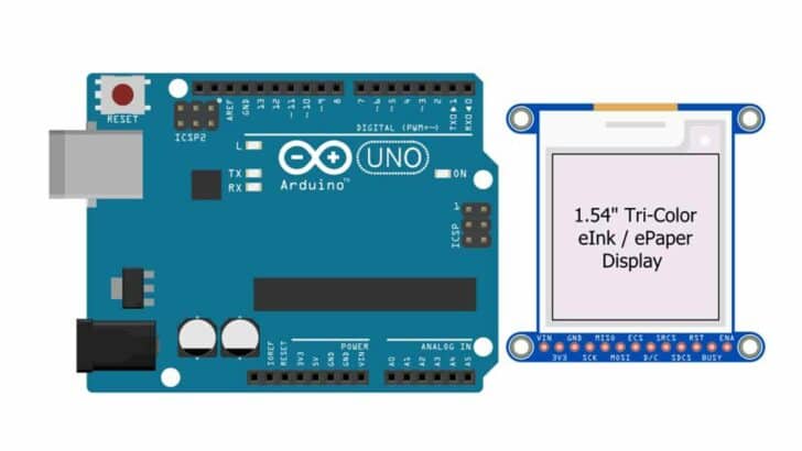
Components Needed To Build Arduino And E-ink Display Project
Hardware Components
- Arduino Uno Rev3 x 1
- 2.9-inch e-ink tri-color display x 1
- Dupont wire x 1 set
- Arduino USB cable (for powering Arduino and programming) x 1
- Breadboard x 1 (optional)
- BergStick Connectors (optional)
Software
Makerguides.com is a participant in the Amazon Services LLC Associates Program, an affiliate advertising program designed to provide a means for sites to earn advertising fees by advertising and linking to products on Amazon.com.
Basics of E-ink Display
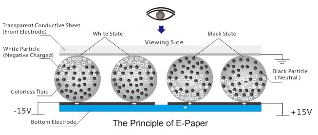
Basic Working Principle Of The E-ink Display
The E-ink stands for electronic ink. The idea is based on a technology where a thin film of microparticles aligns based on the charge.
You can either display black or white in that tiny cell.
The orientation can only be changed once you apply the current in the reverse direction.
Since power is always necessary to clear the Display, you can keep the image/name on the Display as long as you want without worrying about power consumption.
The E-ink display remains the same for weeks or even months without power.
The Display looks more realistic to the eyes. The Display gets better as you move to a well-lit area (same as how you experience while reading a book in a darker and a more lit area).
The Applications Of The E-ink Display
The E-ink display doesn’t need the power to retain the contents on the screen.
Hence it finds its application in many areas where you want to display content that doesn’t change frequently.
Some of the applications are listed below.
Outdoor displays – Fuel price displays, Bus route displays, Information about the monuments, weather information, etc. The displays need no light in the daytime and consume no power while the display is static. It helps to save power and also provides a very readable display even in bright sunlight.
Shelf Labels – The prices won’t change very often. Hence, E-ink displays are an excellent reprogrammable price-label option. The labels can display price information, product name, or both.
Automobiles – Pedometer for cycles, dashboard displays, weather display information system, Next stop display in long route vehicles, booking information of the train seats, etc.
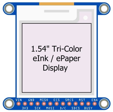
The Pinouts of the E-ink Display
The pin details of the E-ink display are given in the table below. Make sure to buy the E-ink display, which comes with the datasheet.
Let’s get started. Below is the Pinout of the display module where you can see the pin connections and the labels.
| Pin Label | Pin Type | Description |
| VIN | Power | This is the input power pin. You can supply 5 V from the Arduino here. There is a 3.3 V linear voltage regulator on the display module. This pin serves as the input for the regulator. |
| 3V3 | Power | This is the output of the voltage regulator. The 3.3 V powers the display controller IC. You can also use this to power other modules, but ensure that the current consumption is kept below the regulator voltage rating. |
| GND | Power | Ground connection pin. |
| SCK | Signal | SPI Clock – Clock Pin of the serial peripheral interface |
| MISO | Signal | SPI MISO – Master In Slave Out pin of the Arduino. This is the input pin of the Display controller and the output pin of the Arduino. |
| MOSI | Signal | SPI MOSI – Master Out Slave In – This is the Arduino output pin and input pin for the display controller. |
| ECS | Signal | E-ink Chip Select |
| D/C | Signal | E-ink data command |
| SRCS | Signal | SRAM chip select |
| SDCS | Signal | SD Card chip select |
| RST | Signal | E-ink reset |
| BUSY | Signal | E-ink Busy signal |
| ENA | Signal | Enable pin. This is connected to the Enable pin of the 3.3 V regulator. You can drive the pin Low to save Power when you have to. When you disable the display controller, the display RAM and the SD Card (if present) will all get disabled. You have to reinitialize the board again. |
Note that the display controller we have chosen here has an SRAM IC. The SRAM can be used to store the frame buffers. Depending on the display size, the memory required will vary.
For a larger display, the internal RAM present in the Arduino can quickly become a bottleneck.
Hence, many of the display boards will have an SRAM chip.
You can prepare the image/contents in the SRAM. Once ready, you can start loading the display controller with the data from SRAM.
Most of the available display libraries provide this support already.
In the below table, you will find a look-up table for the connection diagram. You can use this table as a reference for other similar E-ink modules.
Most of the pins are configurable. You have to ensure that you also update the code to reflect the pin mapping changes you have made.
| Arduino Pin Connections | E-ink Display module connections |
| Pin 1 of the ICSP header | MISO – SPI Master In Slave Out |
| Pin 3 of the ICSP header | CLK – SPI Clock Pin |
| Pin 4 of the ICSP header | MOSI – SPI Master Out Slave In |
| GND | GND – Ground connection |
| GPIO Pin 5 | SDCS – SD card Chip select pin |
| GPIO Pin 6 | SRCS – SRAM Chip Select |
| GPIO Pin 7 | BUSY – Busy pin connection for E-ink |
| GPIO Pin 8 | RST – Reset Pin of the E-ink controller |
| GPIO Pin 9 | ECS – E-ink Chip select pin |
| GPIO Pin 10 | D/C – Data Command Pin |
In the next section, you will find the step-by-step guide to complete the required connections between Arduino and the E-ink module.
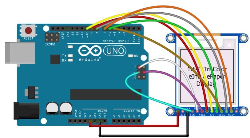
How To Connect The E-ink Display To The Arduino UNO?
The details required to complete the Arduino and the E-ink display are given to you in this section.
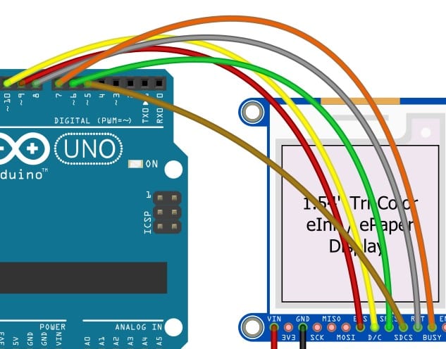
The final connection should look similar to the image below.
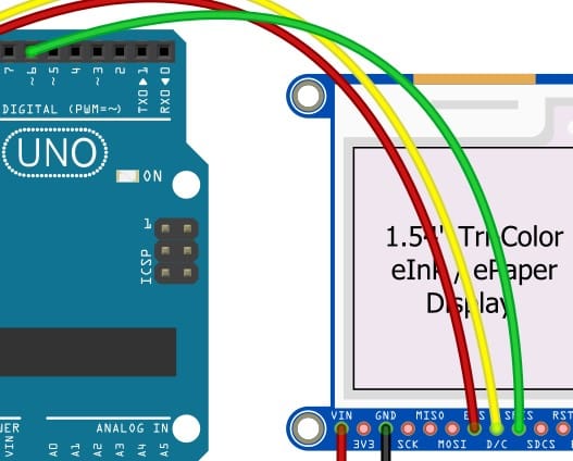
Step 1: Let us begin with the Ground connection
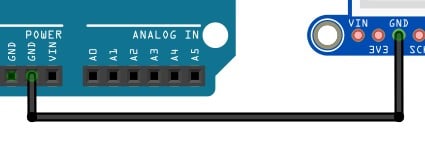
It is a best practice to start the connections with the ground (GND) pins first.
Pin GND of the display goes to the GND pin of the Arduino. You can choose any of the GND pins available.
You can select any of the GND pins available to complete the connection.
Step 2: Connect the 5V pin
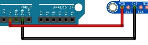
Connect the 5 V pin on the Arduino to the VIN pin of the display module.
The 5 V pin on the Arduino is directly the USB power (when Arduino is powered from the USB cable connected to a computer).
Step 3: Connect the ECS Pin
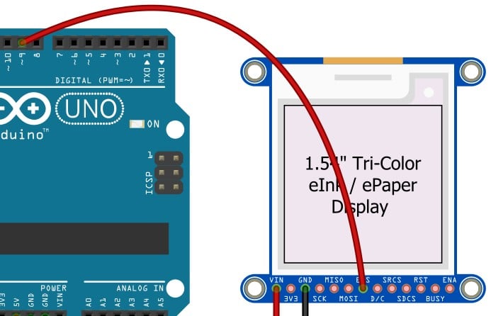
ECS is the chip select pin of the E-ink display controller. Connect this to Pin 9 of the Arduino UNO.
Step 4: D/C Connection between Display and the Arduino
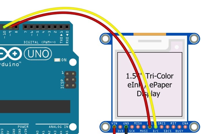
Connect pin 10 on the Arduino UNO to Pin D/C of the E-ink display module. D/C is the Data/Command of the E-ink display.
Step 5: SRCS Pin Connection
SRCS pin is a SRAM Chip select pin. Connect SRCS to Pin 6 of the Arduino
Step 6: Reset pin connection
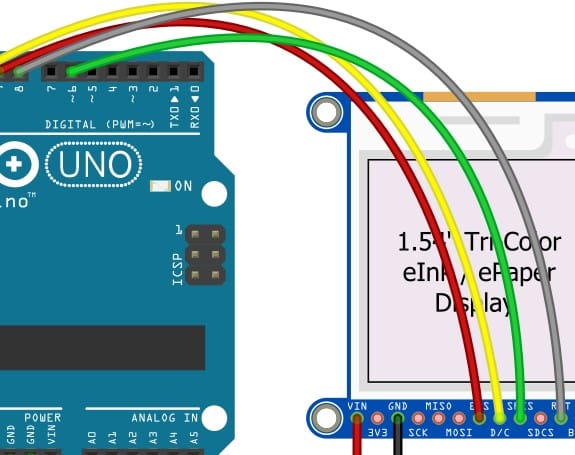
RST pin is the E-ink display controller Reset pin. Connect RST pin to the digital pin 8 of the Arduino UNO.
Step 7: BUSY pin connection
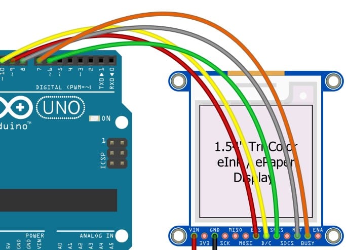
Connect the Display board’s BUSY pin to the digital pin 7 of the Arduino.
Step 8: SDCS Pin connection
The SDCS pin is the chip select pin for the SD Card on the display module. Connect the SDCS pin to the digital pin 5 on the Arduino.
Step 9: ICSP SCK Connection
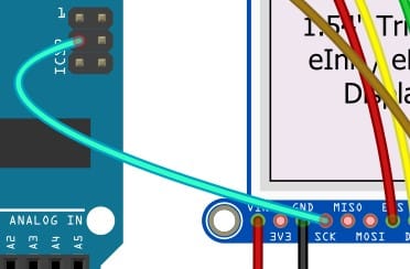
The ICSP SCK is present on a separate 6-pin connector. Connect the SCK pin of the Display module to the ICSP_SCK pin on the Arduino.
Step 10: ICSP MISO Connection
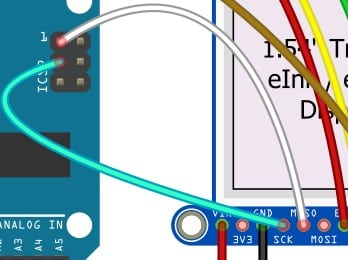
The ICSP MISO is present on the Pin 1 position of the 6-pin connector. Connect the MISO pin of the Display module to the ICSP_MISO pin on the Arduino.
Step 11: ICSP MOSI Connection
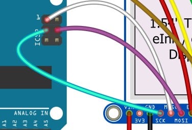
Congratulations! This completes the required hardware connections.
Arduino Code Example For The E-ink Display Project
In this section, you will install the required libraries and run an example code to ensure that the connections and setup are fine. Let us get started.
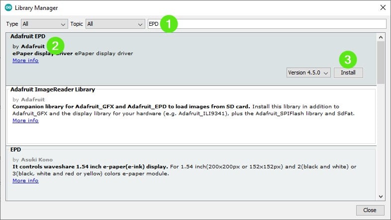
Install the libraries to start with. Go to Tools → Manage Libraries. Search for “EPD” in the search box.
Once you find the Adafruit EPD library, Click on the “Install” button.
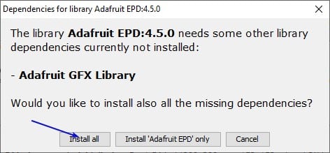
You may be prompted with the option to install all dependent libraries. Click on “Install All” to install all the linked and missing libraries in one shot.
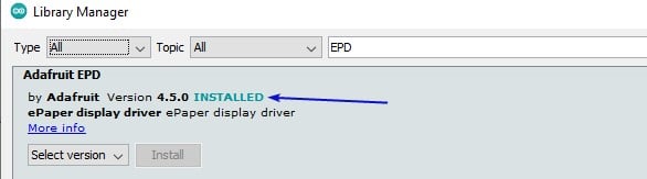
Once the installation is complete, you can verify it by looking at the “INSTALLED” status.
This completes the required library setup. Now we will see the example code.
The Complete Arduino Code
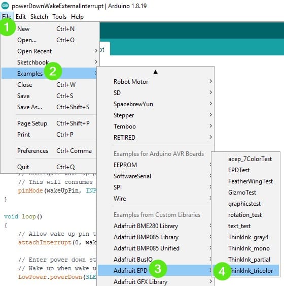
Follow the image below to load an example image from the libraries you have installed in the previous section.
The Code
#include "Adafruit_ThinkInk.h"

#define EPD_DC      10 // can be any pin, but required!
#define EPD_CS      9  // can be any pin, but required!
#define EPD_BUSY    7  // can set to -1 to not use a pin (will wait a fixed delay)
#define SRAM_CS     6  // can set to -1 to not use a pin (uses a lot of RAM!)
#define EPD_RESET   8  // can set to -1 and share with chip Reset (can't deep sleep)

// 1.54" 152x152 Tricolor EPD with ILI0373 chipset
//ThinkInk_154_Tricolor_Z17 display(EPD_DC, EPD_RESET, EPD_CS, SRAM_CS, EPD_BUSY);

// 1.54" 152x152 Tricolor EPD with SSD1680 chipset
//ThinkInk_154_Tricolor_RW display(EPD_DC, EPD_RESET, EPD_CS, SRAM_CS, EPD_BUSY);

// 1.54" 200x200 Tricolor EPD with SSD1681 chipset
//ThinkInk_154_Tricolor_Z90 display(EPD_DC, EPD_RESET, EPD_CS, SRAM_CS, EPD_BUSY);

// 2.13" Tricolor EPD with SSD1680 chipset
//ThinkInk_213_Tricolor_RW display(EPD_DC, EPD_RESET, EPD_CS, SRAM_CS, EPD_BUSY);

// 2.13" Tricolor EPD with IL0373 chipset
//ThinkInk_213_Tricolor_Z16 display(EPD_DC, EPD_RESET, EPD_CS, SRAM_CS, EPD_BUSY);

// 2.7" Tricolor Featherwing or Breakout with IL91874 chipset
//ThinkInk_270_Tricolor_C44 display(EPD_DC, EPD_RESET, EPD_CS, SRAM_CS, EPD_BUSY);

// 2.7" Tricolor Featherwing or Breakout with EK79686 chipset
//ThinkInk_270_Tricolor_Z70 display(EPD_DC, EPD_RESET, EPD_CS, SRAM_CS, EPD_BUSY);

// 2.9" Tricolor Featherwing or Breakout with IL0373 chipset
ThinkInk_290_Tricolor_Z10 display(EPD_DC, EPD_RESET, EPD_CS, SRAM_CS, EPD_BUSY);
// 2.9" Tricolor Featherwing or Breakout with UC8151D chipset
//ThinkInk_290_Tricolor_Z13 display(EPD_DC, EPD_RESET, EPD_CS, SRAM_CS, EPD_BUSY);
// 2.9" Tricolor Featherwing or Breakout with SSD1680 chipset and negative offset
//ThinkInk_290_Tricolor_Z94 display(EPD_DC, EPD_RESET, EPD_CS, SRAM_CS, EPD_BUSY);

//ThinkInk_420_Tricolor_RW display(EPD_DC, EPD_RESET, EPD_CS, SRAM_CS, EPD_BUSY);
//ThinkInk_420_Tricolor_Z21 display(EPD_DC, EPD_RESET, EPD_CS, SRAM_CS, EPD_BUSY);


void setup() {
  Serial.begin(115200);
  while (!Serial) { delay(10); }
  Serial.println("Adafruit EPD full update test in red/black/white");
  display.begin(THINKINK_TRICOLOR);
}

void loop() {
  Serial.println("Banner demo");
  display.clearBuffer();
  display.setTextSize(3);
  display.setCursor((display.width() - 144)/2, (display.height() - 24)/2);
  display.setTextColor(EPD_BLACK);
  display.print("Tri");
  display.setTextColor(EPD_RED);
  display.print("Color");
  display.display();

  delay(15000);

  Serial.println("Color rectangle demo");
  display.clearBuffer();
  display.fillRect(display.width()/3, 0, display.width()/3, display.height(), EPD_BLACK);
  display.fillRect((display.width()*2)/3, 0, display.width()/3, display.height(), EPD_RED);
  display.display();

  delay(15000);

  Serial.println("Text demo");
  // large block of text
  display.clearBuffer();
  display.setTextSize(1);
  testdrawtext("Lorem ipsum dolor sit amet, consectetur adipiscing elit.", EPD_BLACK);
  display.display();

  delay(15000);

  display.clearBuffer();
  for (int16_t i=0; i<display.width(); i+=4) {
    display.drawLine(0, 0, i, display.height()-1, EPD_BLACK);
  }

  for (int16_t i=0; i<display.height(); i+=4) {
    display.drawLine(display.width()-1, 0, 0, i, EPD_RED);
  }
  display.display();

  delay(15000);
}


void testdrawtext(const char *text, uint16_t color) {
  display.setCursor(0, 0);
  display.setTextColor(color);
  display.setTextWrap(true);
  display.print(text);
}
The code snippet below shows the pin mapping. The pin mapping can be updated based on your actual hardware connections.
#define EPD_DC      10 // can be any pin, but required!
#define EPD_CS      9  // can be any pin, but required!
#define EPD_BUSY    7  // can set to -1 to not use a pin (will wait a fixed delay)
#define SRAM_CS     6  // can set to -1 to not use a pin (uses a lot of RAM!)
#define EPD_RESET   8  // can set to -1 and share with chip Reset (can't deep sleep)
The Tri color program output will look similar to this
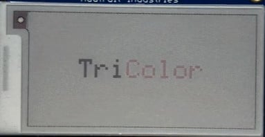
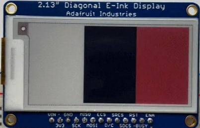
Following all the steps carefully, you should have the output ready. You can tinker with the code to change the code behavior.
FAQs About The Arduino And E-ink Display
I have compiled a list of questions most frequently asked regarding the E-ink displays and their usage with Arduino. I hope these answers will help you to find the answers quickly.
If you have questions still not answered in this section, please post them in the comments section.
I will be glad to answer it for you.
1) How does an E-ink display work?
The E-ink display contains a liquid layer with particular floating microparticles. The particles appear dark or white based on the current you make flow through them.
Depending on the direction of the current flow, either the dark particles or the white particles settle on the top side.
This is the basic idea behind exceedingly power-efficient E-ink displays.
For a detailed description, please refer to the section above, where you can find more information on the E-ink working technology and the latest updates.
2) How do you use Arduino with an E-ink display?
E-ink displays come with the built-in controllers. You can use SPI or I2C communication to transfer the data to the E-ink display controller IC.
This article presents you with an example project where you can drive an E-ink display using Arduino.
3) What are the advantages of E-ink display over TFT?
E-ink displays don’t need the power to retain the information on the screen.
You can practically disconnect the show from the system, and still, the display will hold the data for years.
E-ink displays are easier to read outdoors.
The displays act like a book. Hence, with good lighting, the eyes will not strain.
4) What are the disadvantages of E-ink displays over conventional displays?
E-ink displays appear dull. You need an external light to read the display. The refresh rate of the E-ink display is slow.
The time taken to update the contents on display will be in seconds.
Hence, you cannot use the display in applications where you need to edit the contents faster.
Also, you cannot get a fully colored E-ink display. Hence, the appearance is poor and not attractive.
5) How long does the E-ink display last?
It depends on the module. Most E-ink can keep the display without any external power for months together.
For example, I have a Kindle I have not touched for two years. The display shows the Low battery icon. I don’t see any fading as well.
Depending on the conditions where it is in, the display can last more than a year.
Conclusion
That concludes the article on the E-ink display. I hope this article gave helpful information regarding applications and Arduino E-ink project examples.
I look forward to hearing from you about the next E-ink display project you will build.
I recently saw a large Bus Timings Board made of E-ink Display. The Display was effortless to read.
Isn’t it amazing that the Display was about 15-inch wide yet was taking no power to show the information?
I have an E-ink graphical display which I am using to display my Name!
I believe that the article was easy to follow. If you have any questions, post them in the comments section. If you have suggestions on the article you would like to make, mention them in the comments.
Which topics would you like to read about next? Your suggestions will help me deliver the right content at the right time!
Please share this article with your fellow Arduino enthusiasts!

I am Puneeth. I love tinkering with open-source projects, Arduino, ESP32, Pi and more. I have worked with many different Arduino boards and currently I am exploring, Arduino powered LoRa, Power line communication and IoT.