In this tutorial you will learn how to monitor battery voltage levels for battery-powered projects so that you can recharge the battery in time.
For almost all battery powered projects, be it data loggers for weather, surveillance cameras or robots, you usually want to know what the charging status of the battery is. Preferably, you want to receive a warning, when recharging of the battery is needed.
This prevents over-discharging the battery, which can lead to irreversible damage or reduced battery lifespan. Also, monitoring voltage levels helps us to detect issues related to the power supply, such as faulty connections or inadequate power sources.
In the following sections I will show you two examples for monitoring battery voltage levels. Let’s start with the required parts.
Required Parts
Makerguides.com is a participant in the Amazon Services LLC Associates Program, an affiliate advertising program designed to provide a means for sites to earn advertising fees by advertising and linking to products on Amazon.com. As an Amazon Associate we earn from qualifying purchases.
Below you will find the parts required for this project. Instead of the smaller 16×2 LCD display you could also use a larger 20×4 LCD display. Just make sure it has an I2C interface and not the also common SPI interface.

Arduino Uno

Dupont Wire Set

Breadboard

USB Cable for Arduino UNO
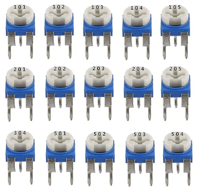
Trimmer Kit
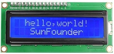
LCD Display
Using the Analog-to-Digital Converter (ADC)
We want to measure the voltage of our battery to know when we need to recharge. We will use an analog input pin for this. But first, let’s quickly talk about the Analog-to-Digital Converters (ADC) that sits behind the analog pin and does all the hard work.
The Analog-to-Digital Converter (ADC) is a built-in feature in many microcontrollers, including Arduino, ESP8266 and ESP32, that allows you to measure analog voltages and convert them into digital values. The ADC works by sampling the analog voltage at regular intervals and then quantizing it into discrete digital values. This process involves several steps:
Sampling
The ADC takes a snapshot of the analog voltage at a specific point in time. The sampling rate determines how frequently the ADC takes these snapshots. A higher sampling rate provides a more accurate representation of the analog signal. For instance, the ADC of an Arduino UNO samples about 15000 times per second.
Quantization
After sampling, the ADC assigns a digital value to the analog voltage. This is done by dividing the voltage range into a specific number of discrete levels. The number of levels depends on the ADC’s resolution. The Arduino Uno has a resolution of 10-bit (0-1023).
Conversion
The ADC converts the analog voltage into a digital value using a process called analog-to-digital conversion. This involves comparing the sampled voltage with a reference voltage and determining the corresponding digital value based on the quantization levels. Be very careful here! The maximum input voltage range is limited. For an Arduino it is 0-5V! If you you go beyond this range you will damage the ADC!
Output
Once the conversion is complete, the ADC outputs the digital value, which can be read by the microcontroller. Note that the accuracy of the ADC’s conversion depends on factors such as its resolution, reference voltage, temperature and noise level.
Using a Voltage Divider
As we have learnt above, the input voltage range for the analog pin is restricted to 0-5V for an Arduino Uno. However, if you run your board on a battery, the battery voltage is typically higher (it will internally reduced by a voltage regulator to a suitable value). The Arduino can take input power voltages from 6 to 20 volts but the analog pin only allows 0-5 volts.
This means we cannot directly connect the battery to an analog input, since its voltage will be higher than permitted! A common method to reduce the input voltage to a suitable range for measurement is to use a Voltage Divider.
It consists of two resistors connected in series, with the battery voltage being measured at the junction between the resistors. The voltage divider reduces the battery voltage down to a level that can be safely measured by the microcontroller’s analog-to-digital converter (ADC).
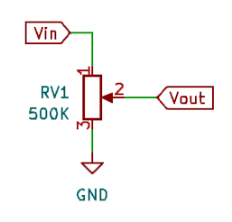
The following picture shows a voltage divider with two resistors R1 and R2. The positive pole of the battery will be connect to Vin and we measure the reduced voltage at Vout.

The voltage divider works based on the principle of voltage division. By using two resistors of known values, the circuit divides the input voltage proportionally between them. The voltage at the junction between the resistors can be calculated using the voltage divider formula:
Vout = Vin * (R2 / (R1 + R2))
Where:
Voutis the output voltage at the junction between the resistors.Vinis the input voltage (battery voltage).R1andR2are the resistances of the two resistors.
Choosing Resistor Values
We know now what a Voltage Divider is and how the voltages and resistor values are related to each other. While the formula works for all kinds of resistor values, in practice you want to pick rather large values.
The reason is that the voltage divider circuit continuously draws current from the battery, which can affect the overall power consumption of your project. The higher the resistor values are, the lower the power consumption. On the other hand, if the resistor value are too high the current will be too low for the ADC to measure the voltage accurately.
Let’s do an example with typical resistor values. If we pick a value for R1 we can calculate R3 as follows:
R2 = (Vout / Vin) * R1
For example, if we select a resistor value 10kΩ for R1 and want to measure a battery voltage of 12V using an ADC with a maximum input voltage of 5V, we get a resistor value of 4167Ω for R2:
R2 = (5V / 12V) * 10000Ω = 4167Ω
Using a Potentiometer as Voltage Divider
While the Voltage Divider with two resistors works fine, it is a bit of a hassle to calculate the correct values, and the solution is rigid. We cannot easily change to a battery with a different voltage, once we have built our Voltage Divider.
A simpler and more flexible solution is to use a Potentiometer instead. It works exactly in the same way but since a Potentiometer is essentially a variable voltage divider, we can adjust it to changes in Vin. Below you can see a Voltage Divider Circuit with a 500KΩ Potentiometer, which will be using in the following circuits.
We just have to make sure that Vout does not exceed the maximum voltage of the analog input pin and the connected ADC. Have a look at our tutorial on How use Arduino to control an LED with a Potentiometer for more details about potentiometers.
Connecting the Voltage Divider to an Arduino to measure its battery voltage is very simple. The following schematics shows the circuit:
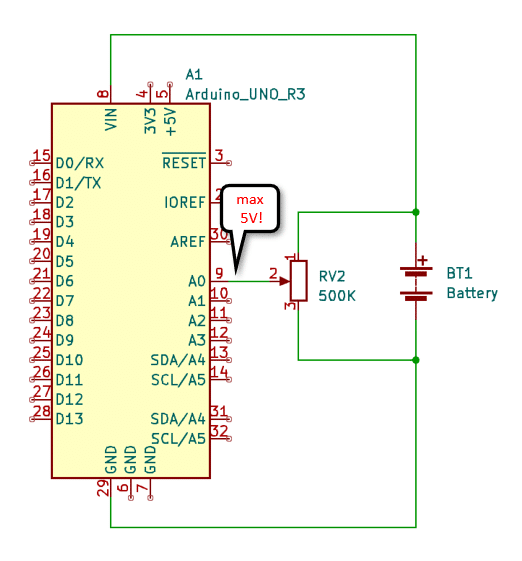
The voltage divider runs in parallel to the battery and its output (2) is connected to the analog input (A0) of the Arduino.
Voltage Divider with Arduino on Breadboard
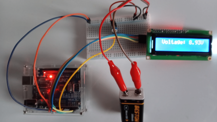
Let’s build this circuit on a breadboard with an Arduino Uno and a 9V battery as power supply. The picture below shows the complete circuit. But before connecting the parts please read on! There are some important details to consider!
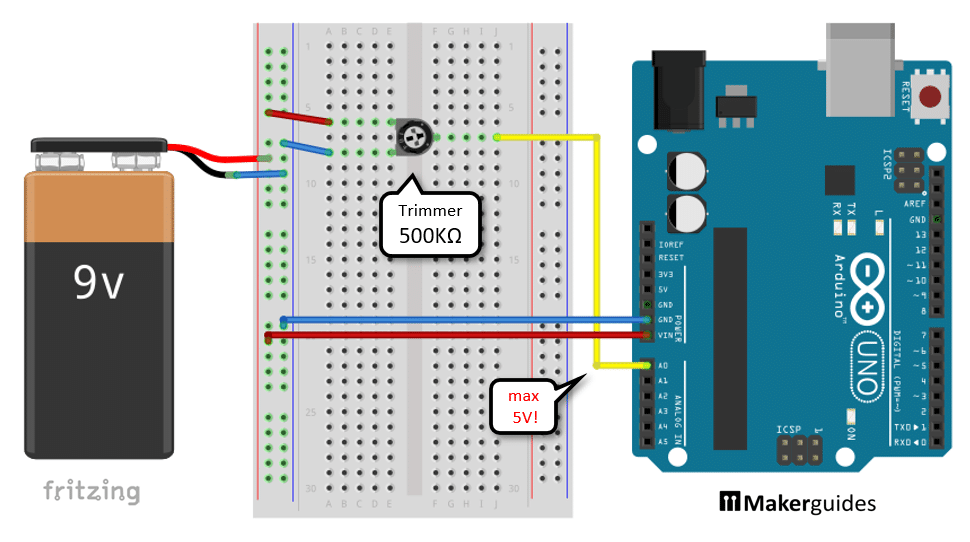
Start by connecting the plus and the minus poles of the 9V battery to the positive and negative power rails of the breadboard. Next connect the positive and negative power rail to the pins of the trimmer/potentiometer as shown above (blue and red wires) but don’t yet connect the yellow wire.
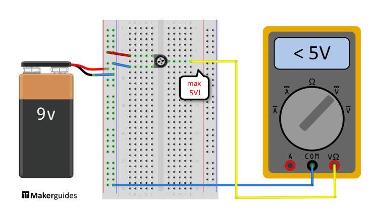
Now before connecting anything else make sure that the output of the Voltage Divider is below 5V! Connect a multimeter to ground and to the Voltage Divider as shown below and verify this!
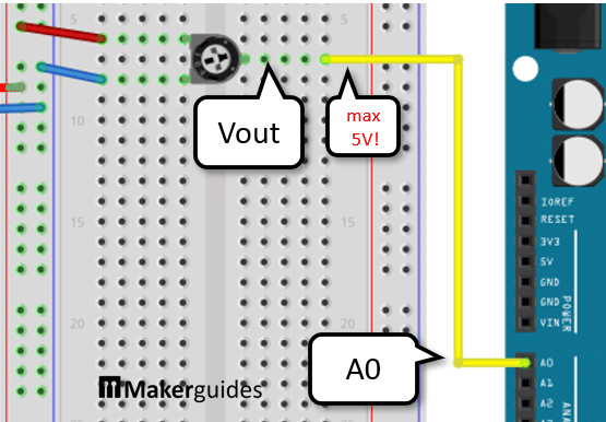
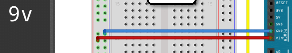
If all looks good, you can then connect the output Vout of the Voltage Divider to the analog input A0 of the Arduino (yellow wire). The input to A0 must be always lower than 5V even for a brand new, fresh battery!
Finally, we connect the negative power rail to GND and the positive power rail to VIN of the Arduino (red and blue wires). Be careful here as well! VIN is not protected against reversed polarity. Make sure the positive pole of the battery is connected to VIN (red wire).
It is okay to connect a battery to VIN of an Arduino Uno and the USB cable to your computer for upload or serial monitoring at the same time (see discussion here). But this may not be the case for other boards!
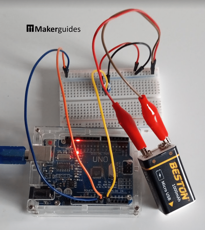
Completed project
Finally, here a picture of the completed project. Note that I am actually using a rechargeable 9V battery. I found them very handy and in the long run cost-effective for Arduino projects, since I don’t have to buy new batteries all the time.
Example 1: Low Battery Warning with Arduino
In this section, we are going to write the code for our battery voltage monitor. Have a quick look at the code below, before we dive into the details.
// Warn if battery voltage drops below a certain threshold
// Voltage is measured at A0
// Built-in LED switches on if voltage is too low

const int threshold = 300;

void setup() {
  Serial.begin(9600);
  pinMode(LED_BUILTIN, OUTPUT);
}

void loop() {
  int value = analogRead(A0);
  Serial.println(value);

  int warn = value < threshold ? HIGH : LOW;
  digitalWrite(LED_BUILTIN, warn);

  delay(1000);
}
In the code above, we monitor the voltage of a battery connected to pin A0. If the voltage drops below a certain threshold, the built-in LED on the Arduino board will turn on as a warning. The loop runs continuously, constantly checking the battery voltage and updating the LED status accordingly.
Let’s break the code down into its parts.
Constants and Variables
The code starts by defining the constant threshold, which specifies the minimum voltage threshold for the battery.
const int threshold = 300;
Setup function
In the setup() function, we initialize the serial communication at a baud rate of 9600, which allows us to send data to the computer for debugging purposes. We also set the mode of the built-in LED (LED_BUILTIN) to OUTPUT, as we will be controlling it.
void setup() {
  Serial.begin(9600);
  pinMode(LED_BUILTIN, OUTPUT);
}
Loop function
The loop() function is where the main logic of the program resides. First, we read the analog value from pin A0, which represents the battery voltage. We then print this value to the serial monitor for debugging purposes.
void loop() {
  int value = analogRead(A0);
  Serial.println(value);
Note that this value is not scaled in any way and while it is proportional to the measure voltages it does not represent a measurement in volt units.
Next, we determine whether the value is below the threshold by comparing the value with the threshold. If the value is below the threshold, we set the warn variable to HIGH, indicating that the LED should be turned on. Otherwise, we set warn to LOW, indicating that the LED should be turned off.
int warn = value < threshold ? HIGH : LOW;
Note that the threshold is not in Volt units either. We don’t care about the actual unit of the measurement here. We only want to determine if the battery needs recharging based on the measured value and the threshold we set.
Finally, we use the digitalWrite() function to control the state of the built-in LED based on the value of warn. If warn is HIGH, the LED will turn on; otherwise, it will turn off.
digitalWrite(LED_BUILTIN, warn);
We add a delay of 1000ms (1 second) to provide a pause between each iteration of the loop.
  delay(1000);
}
That’s it! The program continuously monitors the battery voltage and warns the user if it drops below the specified threshold by turning on the built-in LED. You can set the threshold to any value to like. It will depend on your battery and your board, when you want to warn about low battery status.
Example 2: Battery Voltage Measurement with Arduino
In the previous example, we signalled if the voltage dropped below a certain threshold and didn’t care about the actual voltage. In this example, we will measure the actual voltage and display it on an LCD display in Volt units.
Wiring of the LCD display
The circuit essentially remains that same as in the previous example. We just add the LCD display. The following picture shows the complete wiring.
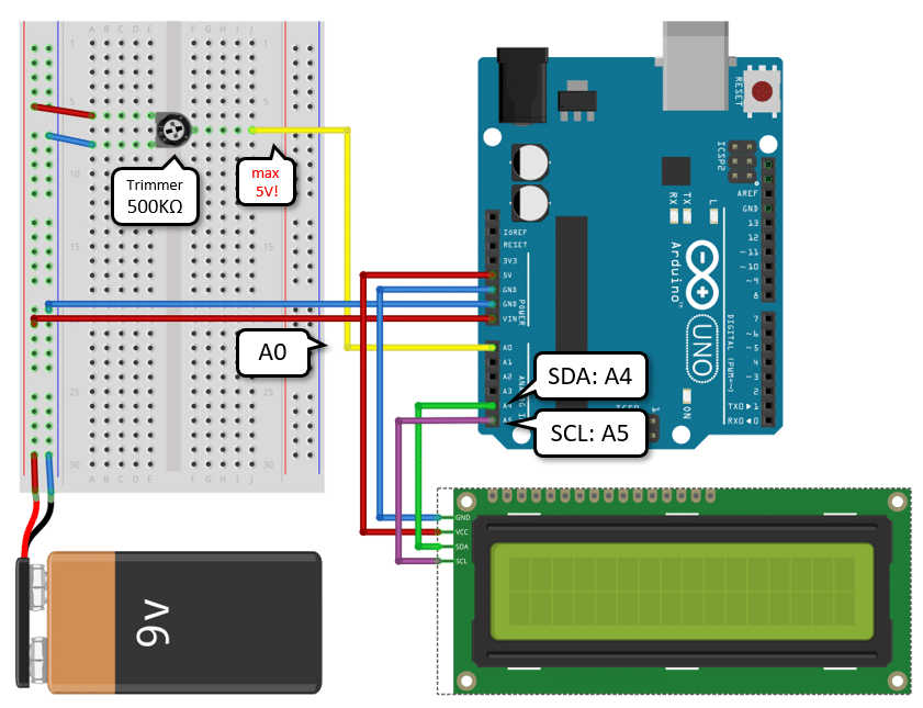
To add the LCD display, first connect VCC and GND of the display to 5V and GND of the Arduino (red and blue wires). Then connect SCL to A5 and SDA to A4.
If you need more details have a look at our tutorial on How to control a character I2C LCD with Arduino. I also used this 20×2 LCD in a tutorial on How to use the MQ-7 Gas Sensor with an LCD display and Arduino, so maybe have look at that one as well, if in doubt.
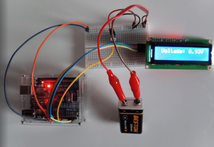
The completed project looks like this:
Code for Measuring Voltages
Below you will find the corresponding code for reading and displaying battery voltages. Have a look first to get a rough overview and we will explain the code in detail in the following sections.
// Measure battery voltage at A0
// and displaying on 20x2 LCD display

#include "LiquidCrystal_I2C.h"

const double maxV = 9; // 9V max

LiquidCrystal_I2C lcd = LiquidCrystal_I2C(0x3F, 20, 4);

void setup() {
  lcd.init();
  lcd.backlight();
}

void loop() {
  int value = analogRead(A0);
  double voltage = value * maxV/1023.0;

  lcd.clear();
  lcd.setCursor(1, 0);
  lcd.print("Voltage:");
  lcd.setCursor(10, 0);
  lcd.print(voltage);
  lcd.setCursor(14, 0);
  lcd.print("V");

  delay(1000);
}
To understand the code in detail, let’s have a look at its parts. We start with the constants and variables.
Constants and Variables
First we define the constant maxV that specifies the maximum voltage of the battery. In this case, it is set to 9V. If you use a different battery (6V, 12V, …), you have to adjust this value!
const double maxV = 9; // 9V max
Library and LCD Initialization
We include the LiquidCrystal_I2C.h library, which provides functions for controlling the LCD display. You will need to install this library, if you haven’t already. See our tutorial on How to control a character I2C LCD with Arduino for details.
We then create an instance of the LiquidCrystal_I2C class and initialize it with the I2C address of the LCD display (0x3F) and the number of columns and rows (20 and 4, respectively). Another common I2C address for LCD displays is 0x27. So, if 0x3F doesn’t work for you try 0x27, or use an I2C scanner to find the correct address of your display.
#include "LiquidCrystal_I2C.h"

LiquidCrystal_I2C lcd = LiquidCrystal_I2C(0x3F, 20, 4);

void setup() {
  lcd.init();
  lcd.backlight();
}
Loop function
In the loop() function, we first read the analog value from pin A0 using the analogRead() function. This value is proportional to the the battery voltage. We then calculate the voltage by multiplying the analog value by the maximum voltage and dividing it by the maximum range of the analog input (1023).
void loop() {
  int value = analogRead(A0);
  double voltage = value * maxV/1023.0;
Next, we clear the LCD display using the clear() function and set the cursor position to display the voltage. We print the voltage value on the LCD display by using the print() function. Finally, we add the unit “V” to indicate that the value is in volts.
  lcd.clear();
  lcd.setCursor(1, 0);
  lcd.print("Voltage:");
  lcd.setCursor(10, 0);
  lcd.print(voltage);
  lcd.setCursor(14, 0);
  lcd.print("V");
We add a delay of 1000ms (1 second) using the delay() function to control the refresh rate of the battery voltage on the LCD display.
  delay(1000);
}
That’s it! We have the code to read and display voltages but now we have to calibrate the system for accurate readings.
Calibration of Battery Voltage Monitor
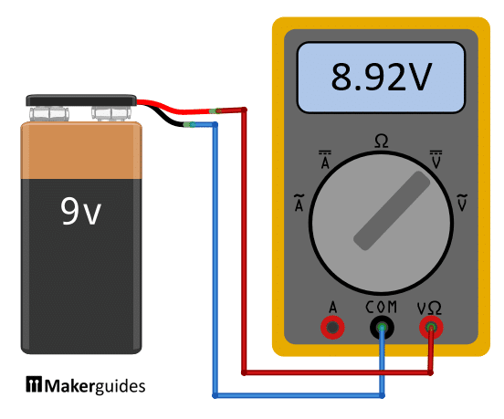
The calibration is simple. First disconnect the battery from your project and connect it to a multimeter instead. Measure the voltage of the battery. In the example below, we measure 8.92V.
Then reconnect the battery back to the Arduino project. Now very slowly turn the trimmer until the display shows a voltage as closely as possible to the one you just measured. That finishes the calibration.
Note that the resolution of the voltage meter we just built is fairly low (1023 steps) and that the ADC within an Arduino Uno is not perfectly linear. So, this project is not suited for highly accurate voltage measurements but perfectly fine to monitor the voltage of a battery.
Example 3: Voltage Measurement using CPUVolt for Arduino
In the two examples above, we used a voltage divider to derive a voltage that can be read on an analog input pin to monitor battery levels. Using a voltage divider has the advantage that it works for essentially all microcontrollers (Arduino, ESP32, ESP8622, …). The disadvantage is, that you need the additional hardware (resistors) for the voltage divider.
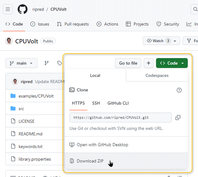
If you are using a ATMega processor (Atmel), such an Arduino, then there is a cool little library called CPUVolt, that allows you to monitor battery levels without needing a voltage divider. To install the CPUVolt library, go to the github repo at https://github.com/ripred/CPUVolt and click on “Code” and then “Download ZIP”.
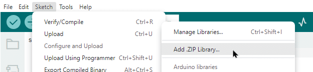
Install the dowloaded file CPUVolt-main.zip using the Arduino IDE by going to Sketch -> Include Library -> Add.ZIP library …:
Now we are ready to build the circuit and write the code.
Wiring for Battery Charge Measurement
The wiring for measuring and displaying battery voltage levels is essentially the same as in Example 2. We just leave out the Voltage Divider and don’t need the breadboard anymore. See the picture below.
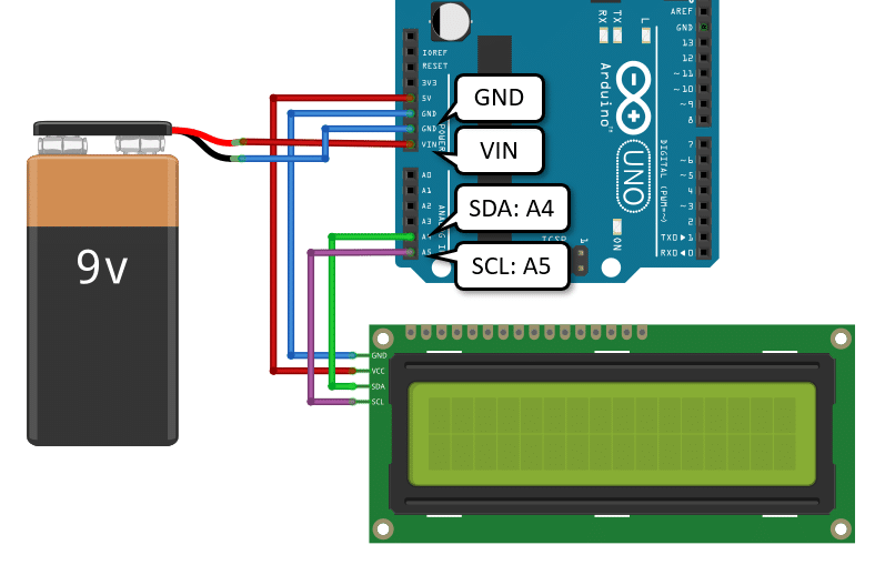
We connect the battery to VIN and GND, and the LCD display to SDA and SCL, as before. Just watch out for the voltage on the VIN pin. Depending on the Arduino board you are using the maximum allowed voltage varies! For an Arduino Uno it is between 7V and 12V.
In most battery powered projects you may not need or want to use an LCD display. But it will come in handy to calibrate the battery level measurements.
Code for Battery Charge Measurement
// Measuring battery charge levels

#include "CPUVolt.h"
#include "LiquidCrystal_I2C.h"

LiquidCrystal_I2C lcd = LiquidCrystal_I2C(0x3F, 20, 4);

void setup() {
  lcd.init();
  lcd.backlight();
}

void loop() {
  lcd.clear();

  // 5209 -> 9V, 4935 -> 6V
  float pct = readPercent(4935, 5209);
  lcd.setCursor(1, 0);
  lcd.print("Percent:");
  lcd.setCursor(10, 0);
  lcd.print(pct);

  long mv = readVcc();
  lcd.setCursor(1, 1);
  lcd.print("Voltage:");
  lcd.setCursor(10, 1);
  lcd.print(mv);

  delay(1000);
In the code above, we are measuring the battery charge levels and displaying them on an LCD screen using the CPUVolt library and the LiquidCrystal_I2C library.
To understand the code in detail, let’s have a look at its parts.
Library Inclusion
We start by including the necessary libraries for our project. We include the “CPUVolt.h” library to measure the battery charge levels and the “LiquidCrystal_I2C.h” library to control the LCD screen.
#include "CPUVolt.h"
#include "LiquidCrystal_I2C.h"
LCD Initialization
In the setup() function, we initialize the LCD screen. We call the init() function to initialize the LCD and the backlight() function to turn on the backlight.
void setup() {
  lcd.init();
  lcd.backlight();
}
Main Loop
In the loop() function, we perform the main operations of our program. We start by clearing the LCD screen using the clear() function.
void loop() {
  lcd.clear();
}
Battery Charge Level Measurement
Next, we measure the battery charge level using the readPercent() function from the CPUVolt library. We pass the minimum and maximum voltage values for our battery as parameters to the function. The returned value is stored in the variable pct.
// 5209 -> 9V, 4935 -> 6V
float pct = readPercent(4935, 5209);
This is where you calibrate the battery charge levels. In my case, I powered the Arduino with 9V, which gave me a reading of 5209 mV for the 100% charge, and with 6V, which gave me a reading of 4935 mV, which corresponds to 0% charge.
Displaying Battery Charge Level
We then display the battery charge level on the LCD screen. We set the cursor position using the setCursor() function and print the text “Percent:” and the value of pct using the print() function.
lcd.setCursor(1, 0);
lcd.print("Percent:");
lcd.setCursor(10, 0);
lcd.print(pct);
Battery Voltage Measurement
Next, we measure the battery voltage using the readVcc() function from the CPUVolt library. The returned value is stored in the variable mv (milli Volt).
long mv = readVcc();
Displaying Battery Voltage
We then display the battery voltage on the LCD screen. We set the cursor position and print the text “Voltage:” and the value of mv using the setCursor() and print() functions.
lcd.setCursor(1, 1);
lcd.print("Voltage:");
lcd.setCursor(10, 1);
lcd.print(mv);
Delay
Finally, we add a delay of 1 second using the delay() function to control the refresh rate of the LCD screen.
delay(1000);
Accuracy and Sensitvity
While the CPUVolt library works, the accuracy or sensitivity is very limited. In my case, I could drop the supply voltage from 9V down to 6.4V and the percentage for the battery charge was still at 100%. From 6.4 down to 6V the displayed charge level then dropped rapidly down to 0%.
For practical applications, I would prefer a more linear sensitivity, where the displayed percentages start to drop earlier and provides a better estimate of the remaining battery life. But if you are in a pinch and need a low battery warning without an extra a voltage divider, the CPUVolt library is great.
Conclusion
Monitoring battery voltage is crucial for battery-powered projects to ensure optimal performance and prevent unexpected shutdowns. In this blog post, we provided two example for monitoring battery voltage for Arduino.
One example is a simple warning system that alerts when battery levels are too low. The other example actually measures the battery voltage and displays it on an LCD display.
In both cases we used a voltage divider circuit, which allows you to scale down the battery voltage to a range that can be measured by the microcontroller. This method provides more flexibility in terms of voltage range, but it requires additional components and careful selection of resistor values.
Finally, I showed you how to use the CPUVolt library to monitor battery charge levels without the need of an external Voltage Divider circuit.
To achieve accurate battery voltage monitoring, it is important to consider factors such as temperature compensation, noise filtering, and power supply stability. Taking these factors into account will help you obtain reliable and consistent readings.
In conclusion, monitoring battery voltage is essential for battery-powered projects. By choosing the right voltage monitoring method, testing and calibrating the system, and implementing low battery warning functionality, you can ensure optimal performance and reliability for your projects.
So, go ahead and start monitoring battery voltage in your projects !
Frequently Asked Questions
Here are some frequently asked questions about monitoring battery voltage for battery-powered projects:
Q: Why is it important to monitor battery voltage?
A: Monitoring battery voltage is crucial for battery-powered projects because it allows you to keep track of the battery’s state of charge. By monitoring the voltage, you can determine when the battery is running low and needs to be recharged or replaced. This helps prevent unexpected shutdowns and ensures the reliability of your project.
Q: How does the Analog-to-Digital Converter (ADC) method work?
A: The ADC method involves connecting the battery’s voltage to one of the analog input pins of the microcontroller. The microcontroller then converts the analog voltage into a digital value, which can be read and processed in your code. By mapping the digital value back to the actual voltage range, you can accurately monitor the battery voltage.
Q: What is a voltage divider circuit?
A: A voltage divider circuit is a simple circuit that consists of two resistors connected in series. By connecting the battery’s voltage across one of the resistors, you can create a voltage divider that produces a fraction of the battery voltage as an output. This output voltage can be measured and used to monitor the battery voltage.
Q: How can I test and calibrate the voltage monitoring system?
A: To test and calibrate the voltage monitoring system, you can use a known voltage source, such as a multimeter, to compare the measured voltage with the actual voltage. Adjusting the resistors in the voltage divider circuit or applying calibration factors to the ADC readings can help improve the accuracy of the voltage monitoring system.
Q: What are some tips for accurate battery voltage monitoring?
A: To ensure accurate battery voltage monitoring, consider the following tips:
- Use stable and accurate voltage references for calibration.
- Minimize noise and interference in the voltage measurement circuit.
- Account for voltage drops across components and connections.
- Implement proper power management techniques to conserve battery life.
- Regularly test and calibrate the voltage monitoring system to maintain accuracy.
By following these tips, you can achieve more reliable and accurate battery voltage monitoring for your projects.
These frequently asked questions should provide you with a better understanding of battery voltage monitoring for your battery-powered projects. If you have any additional questions, feel free to ask in the comments section below.
Stefan is a professional software developer and researcher. He has worked in robotics, bioinformatics, image/audio processing and education at Siemens, IBM and Google. He specializes in AI and machine learning and has a keen interest in DIY projects involving Arduino and 3D printing.