In this tutorial you will learn how to read the speed or tachometer signal of a 3- or 4-wire fan using an Arduino.
Fans are an essential component in many electronic devices, providing cooling and ventilation to prevent overheating. Monitoring the speed of a fan can be crucial for maintaining optimal performance and preventing potential failures.
Required Parts
Below the list of required parts. I added the LEDs in case you want to blink a warning LED, if the fan speed drops below a certain threshold.

Arduino Uno

Dupont Wire Set

Breadboard

USB Cable for Arduino UNO

Resistor & LED kit
Makerguides.com is a participant in the Amazon Services LLC Associates Program, an affiliate advertising program designed to provide a means for sites to earn advertising fees by advertising and linking to products on Amazon.com. As an Amazon Associate we earn from qualifying purchases.
Types of Fans
There are many, many different types of fans. In the following we will focus on the fans commonly used for cooling in computers, 3D printers, small evaporative coolers and such. Most of these fans are brushless DC fans that come with 2, 3 or 4 wires and run on 12V.
2-Wire DC Fan
2-wire DC fans are the simplest type of DC fans. They have two wires. One red wire for power (VCC) and one black wire for ground (GND). Below is a picture of a typical 2-wire fan.
These fans run at a fixed speed but the speed can be changed via Pulse Width Modulation (PWM). See our tutorial on How To Control Fan using Arduino. 2-wire fans do not provide a speed signal you can read directly. However, you use a magnet and a Hall sensor to create your own: Build Arduino Tachometer Using A3144 Hall Effect Sensor
3-Wire DC Fan
3-wire DC fans have the usual two wires for power and ground (red and black) and an additional wire (typically yellow) called the tachometer (TACH) wire. This wire provides a pulse signal that indicates the fan’s rotational speed. By reading this signal, you can monitor the fan speed or RPM (Revolutions Per Minute).
The tachometer signal is generated by a Hall effect sensor or an optical sensor that detects the passing of specific markings or magnets on the fan’s rotor or motor. The output is a pulse, and the frequency of the pulses (and the pulse length) corresponds to the speed of the fan.
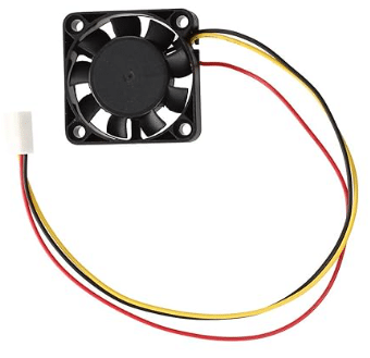
Most computer cooling fans are 3-wire fans but they are used in many other devices as well. Below a picture of a small 3-wire, 12 DC fan for a 3D printer:
4-Wire DC Fan
4-wire fans are the most advanced type of fans and provide additional functionality. They have four wires: one for power (usually red), one for ground (usually black), one for the fan speed signal (usually yellow), and one for speed control (usually blue).
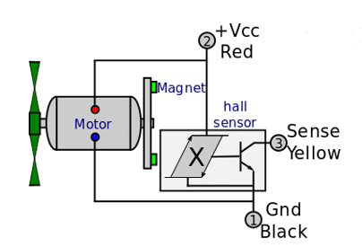
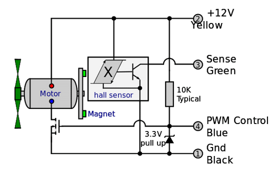
Fan speed is regulated by sending a PWM (Pulse Width Modulation) signal on the speed control wire, which is connected to a MOSFET that controls the motor. See the following circuit diagram.
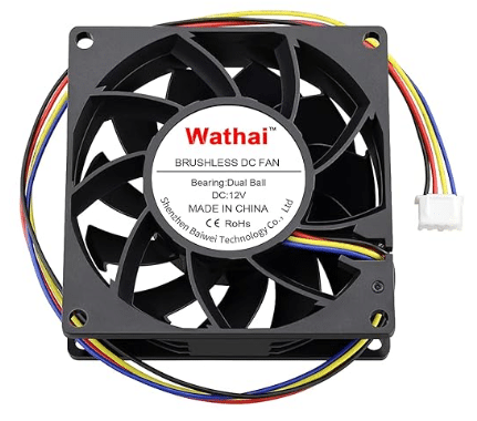
Below a picture of a typical 12V 4-wire DC fan used as a computer cooling fan:
You can control the speed of a 2- or 3-wire fan in the same way by building the controlling circuit yourself. Have a look at our tutorial on How To Control Fan using Arduino for more details.
In summary, 2 and 3-wire fans typically run at constant speed. 3-wire fans provide a tachometer signal to monitor to the fan speed. And 4-wire fans typically run at variable speed, controlled via a PWM signal on the fourth wire but also allow to monitor fan speed via the third wire.
Understanding the Fan Speed Signal
As mentioned above, inside a 3- or 4-wire fan is typically a Hall Effect Sensor that detects the passing of two magnets attached to rotating part of the fan to measure the fan speed. Two magnets are usually used to avoid an uneven mass distribution of the rotating parts, which would cause vibrations. See the picture below.
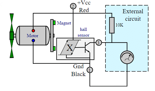
The speed signal can be measured by using a pull-up resistor and connecting an oscilloscope as shown in the circuit above. Here a photo of my oscilloscope while displaying the tachometer signal of a small fan.
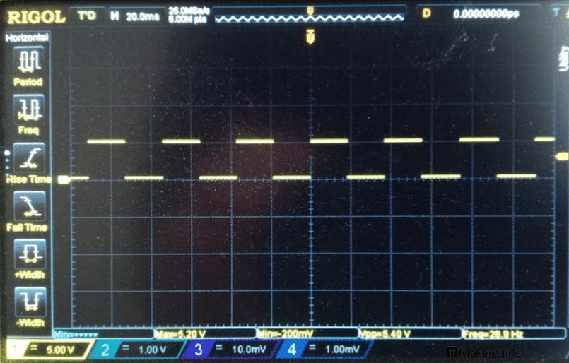
As you can see the tachometer or speed signal is a rectangular pulse with a 50% duty cycle and a frequency that corresponds to the rotational speed of the fan. The faster the fan spins, the shorter the pulse length will become and vice versa.
If you look closely, you will see that the peak voltage of the pulse is around 5V, while the fan is a 12V fan. This is because, I am using a slightly different circuit, which we will discuss in detail in the next section.
Connecting the Speed Signal to an Arduino
In this section, I show you how to connect the speed signal (tachometer signal) of a 3 or 4-wire fan to an Arduino to measure the fan speed.
You cannot just connect the yellow wire of a 3 or 4-wire fan to a digital input of an Arduino to read the fan speed. It will not work! You need a pull-up resistor. The wiring diagram below shows you how that is done.
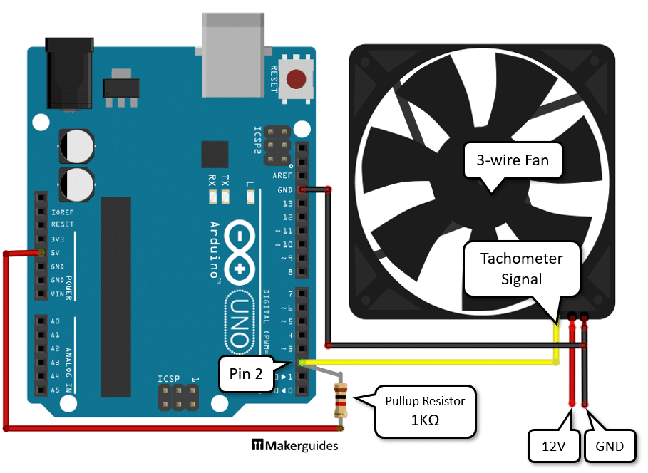
Connect a resistor of 1KΩ or 10KΩ to the +5V pin and to pin 2 of your Arduino. In the example above, I am using a 1KΩ resistor but any resistor between 1KΩ and 10KΩ is fine and commonly used for pull-up resistors. Then connect the yellow tachometer wire of the fan also to pin 2 of the Arduino. And we also need to connect the black ground (GND) wire of the fan to the GND pin of the Arduino. Finally, connect the fan to its required voltage. In the example above that is 12V.
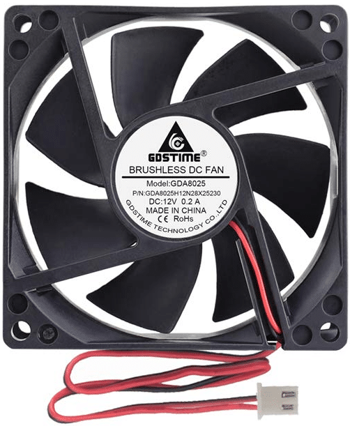
Fan rating
But check the label on your fan to find out which voltage is required in your case. The picture below shows the label of one of my fans that it is rated for 12V with a current of 0.18A = 180mA.

Typical voltages are 5V, 6V, 12V and 24V and currents will be around 200 or 300mA for computer cooling fans. Note that you cannot use a GPIO pin of your Arduino as a power source for a fan. The fan draws too much current and will damage your Arduino! You can use the 5V pin of your Arduino Uno if your fan draws less than 500mA (and is a 5-6V fan).
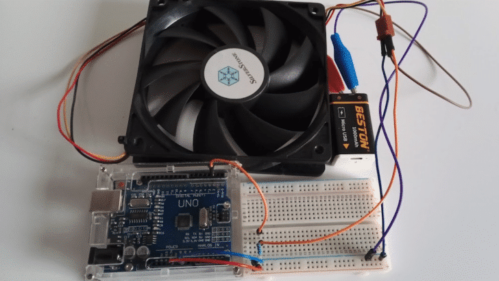
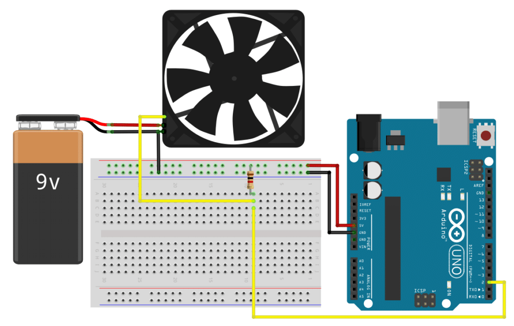
Circuit on breadboard
You can try this circuit with a 12V fan and a 9V battery, if you don’t have a 12V power supply or battery. The fan will spin, just a bit slower. The image below shows the complete wiring on a breadboard. It is the same circuit as before just with the addition of the battery and on a breadboard.
In the next section we write the code to measure the fan speed using this circuit.
Code to Read Fan Speed Signal
Here we will read the fan speed signal to measure the RPM (Revolutions Per Minute) of the fan. This assumes that you have a 3-wire or 4-wire fan that provides a tachometer output signal. If you have a 2-wire fan, don’t worry. You can create a tachometer signal yourself. See our tutorial Build Arduino Tachometer Using A3144 Hall Effect Sensor.
As you have seen above, the speed or tachometer signal is a rectangular pulse. If we count how many pulses we get within a minute we can calculate the number of times the fan rotates within a minute. This measurement of speed is called RPM (Revolutions Per Minute).
The easiest way to count pulses is to look for a raising or falling edge in the signal. The picture below shows a rectangular pulse with a falling edge marked.
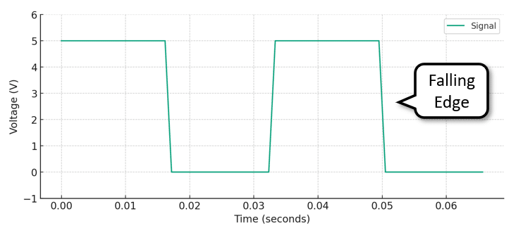
Counting falling edges is the same as counting pulses. The following code does that by attaching an interrupt to the tachometer signal that increments a counter, whenever a falling edge is detected. Have a quick look at the code first and then we discuss the details.
const int tachoPin = 2;
volatile unsigned long counter = 0;

void countPulses() {
  counter ++;
}

void setup() {
  Serial.begin(9600);
  attachInterrupt(digitalPinToInterrupt(tachoPin), countPulses, FALLING);
}

void loop() {
  delay(1000);
  long  rpm = counter * 60 / 2;
  Serial.print("RPM:");
  Serial.println(rpm);
  counter = 0;
}
Constants and Variables
We start with the constants and variables. First, we define the constant tachoPin that specifies which pin the tacho signal of the fan is connected to. We also define a variable counter to keep track of the number of pulses received from the tacho signal. It needs to be of the type “volatile“, since it is used within an interrupt service routine (ISR).
const int tachoPin = 2;
volatile unsigned long counter = 0;
Count Pulses Function
In the countPulses() function, we increment the counter variable by one each time a pulse is received from the tacho signal. This function is called whenever a falling edge is detected on the tachoPin using the attachInterrupt() function.
void countPulses() {
  counter ++;
}
Setup Function
In the setup() function, we initialize the serial communication at a baud rate of 9600 using Serial.begin(). This allows us to print the RPM values to the serial monitor and serial plotter. We also attach an interrupt to the tachoPin using attachInterrupt() and specify that the interrupt should be triggered on a FALLING edge. Whenever a falling edge is detected on the tachoPin, the countPulses() function will be called. You could use the RAISING edge instead, if you wanted to.
void setup() {
  Serial.begin(9600);
  attachInterrupt(digitalPinToInterrupt(tachoPin), countPulses, FALLING);
}
Loop Function
In the loop() function, we first wait for 1000ms = 1 second using delay(). During that second of delay the interrupt service routine countPulses() is running in the background, counting the falling edges of the tachometer signal.
We then calculate the RPM by multiplying the counter variable by 60 (to convert from pulses per second to pulses per minute) and dividing by 2 (since each rotation of the fan generates 2 pulses). We print the calculated RPM value to the serial monitor using Serial.print() and Serial.println(). Finally, we reset the counter variable to 0 to start counting pulses for the next time period (1 second).
void loop() {
  delay(1000);
  long rpm = counter * 60 / 2;
  Serial.print("RPM:");
  Serial.println(rpm);
  counter = 0;
}
Note that some fans report only one pulse per rotation. In this case, you need to remove the division by 2, since each pulse then means one rotation of the fan.
If your speed readings vary a lot you could increase the delay time. For instance, a delay of 2 seconds will give you more stable readings but you need to change the multiplier then from 60 to 30. Similarly, if you want faster speed readings, you could reduce the delay to 500ms but the have change the multiplier from 60 to 120.
Example output
If I run this code with my fan and use my finger to temporarily slow down the fan by pressing on the center axle, I see the following output on the Serial Plotter:
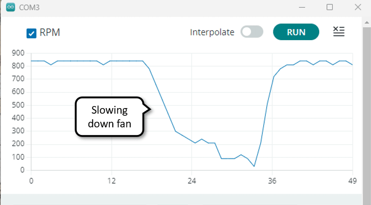
And there you have it! Now you know how to measure the speed of a 3- or 4-wire fan using its tachometer signal and an Arduino.
Conclusions
In this blog post, we have learned how to read fan speed (tachometer) signals with Arduino. We started by understanding the different types of fans, including 2, 3, and 4 wire fans.
We then looked at the fan speed signal itself. Fan speed signals are typically provided as rectangular pulses with a frequency proportional to the fan speed and measured in Revolutions per Minute (RPM).
Next, we discussed how to connect the fan speed signal wire to the Arduino. We provided a step-by-step guide on how to make the necessary connections.
Finally, we covered the process of writing the code for reading the fan speed signal. We explained how to use interrupts to capture the pulses from the fan and calculate the speed based on the number of pulses received within a second.
If you have any further questions or need clarification on any of the topics covered in this blog post, please refer to the Frequently Asked Questions section below.
Frequently Asked Questions
Here are some frequently asked questions about reading fan speed signals with Arduino:
Q: What types of fans can I read the speed signal from?
A: You can read the speed signal from 3, and 4 wire fans. These are common types of fans used in various electronic devices and computer systems.
Q: How do I identify the speed signal wire on a fan?
A: The speed signal wire is usually labeled as “TACH” or “SIGNAL” on the fan. It is typically yellow, while the power and ground wires are red and black. If it is a 4-wire fan you usually see an additional blue wire for speed control.
Q: How do I warn if the fan speed is too low?
Here is a code example the switches on the built-in LED if the fan speed drops below 500 RPM:
const int tachoPin = 2;
volatile unsigned long counter = 0;

void countPulses() {
  counter ++;
}

void setup() {
  pinMode(LED_BUILTIN, OUTPUT);
  attachInterrupt(digitalPinToInterrupt(tachoPin), countPulses, FALLING);
}

void loop() {
  delay(1000);
  long rpm = counter * 60 / 2;
  counter = 0;

  int warn = rpm < 500 ? HIGH : LOW;
  digitalWrite(LED_BUILTIN, warn);
}
Q: Can I connect multiple fans to the Arduino for reading their speed signals?
A: Yes, you can connect multiple fans to the Arduino by using separate digital input pins for each fan’s speed signal wire. Make sure to adjust your code accordingly to read the speed signals from multiple pins.
Q: What is the voltage level of the fan speed signal?
A: The voltage level of the fan speed signal is determined by the voltage the pull-up resistor is connected to. To read a tachometer signal with an Arduino, you want to use a 5V signal. For other microprocessors, such as the ESP32, you would use a 3.2V signal.
Q: How do I calculate the fan speed from the speed signal?
A: The fan speed is usually provided as a series of pulses per revolution (PPR) or rotations per minute (RPM).
Q: Can I control the fan speed using Arduino?
A: Reading the fan speed signal with Arduino allows you to monitor the fan speed but does not directly control it. If you want to control the fan speed, you may need additional circuitry, such as a motor driver or PWM controller, depending on the fan type.
However, if you control the fan speed with a PWM signal, this will interfere with the speed measurement. You will need to pause the PWM during speed measurement or use a 4-wire fan that has a separate speed control wire.
Q: Are there any safety precautions I should consider when working with fans and Arduino?
A: Yes, don’t power the fan from the GPIO pins of your Arduino! Use a separate power supply or battery with suitable voltage and current and make sure to connect the ground wires of the power supply and the Arduino ground. Also do not use the circuits presented above with an AC Fan that runs on 110V or 220V!
If you have any more specific queries, feel free to ask in the comments section below.
Stefan is a professional software developer and researcher. He has worked in robotics, bioinformatics, image/audio processing and education at Siemens, IBM and Google. He specializes in AI and machine learning and has a keen interest in DIY projects involving Arduino and 3D printing.