Do you want to know about the oxygen level in your blood and the status of your heart rate at your home? I’m going to show you how to make a homemade heart rate monitoring system with Arduino and the Max30100 Sensor.
I’ll show you exactly which components you need, pin out diagrams, how to wire everything up, and example code as well. Let’s get started.
Supplies
Hardware components
| Arduino Uno Rev3 | × 1 | Amazon |
| USB cable type A/B | × 1 | Amazon |
| MAX30100 Heart Rate Oximeter Sensor Module | × 1 | Amazon |
| MAX30102 Heart Rate Oximeter Sensor Module | × 1 | Amazon |
| 16×2 LCD Display | × 1 | Amazon |
| Breadboard | × 1 | Amazon |
| Jumper wires | × 15 | Amazon |
| 10K Potentiometer | × 1 | Amazon |
| Power supply 5V (Optional) | × 1 | Amazon |
Software
| Arduino IDE | Arduino IDE |
Makerguides.com is a participant in the Amazon Services LLC Associates Program, an affiliate advertising program designed to provide a means for sites to earn advertising fees by advertising and linking to products on Amazon.com.
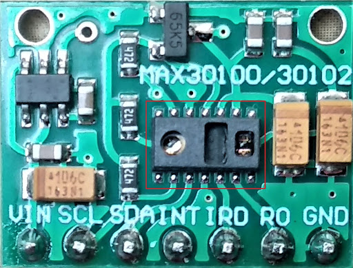
About MAX30100 Sensor Module
The MAX30100 is an integrated heart rate and pulse oximetry sensor module. It comprises two LEDs, a photodetector, an optimized optical element, and low noise analog signal processing to detect heart rate and pulse oximetry signals. It operates from 1.8V to 3.3V, and it communicates through the I2C standard.
How does a MAX30100 work?
Pulse Oximeter measures oxygen saturation in our body. Oxygen enters the lungs and afterward is passed into the blood.
The blood conveys oxygen to the different organs in our body. The primary way oxygen is carried in our blood is by using hemoglobin.
You need to put your finger on the glass surface of the sensor, which allows the little light emissions through the blood and measures the oxygen level.
The oxygen level depends on the amount of light absorption in oxygenated or deoxygenated blood.
This sensor gives oxygen level as SpO2 parameter in percentage and heart rate in beats per minute (BPM).
How does MAX30100 measure heart rate?
The device has two LEDs, one LED emits red light, and another emits infrared light, which measures the pulse rate. Both lights are used to measure oxygen levels in the blood.
When the heart pumps blood, there is an increase in oxygenated blood as a result of having moderate blood.
With the heart relaxing over time, the volume of oxygenated blood also decreases. The pulse rate is determined according to the time between the increase and decrease of oxygenated blood.
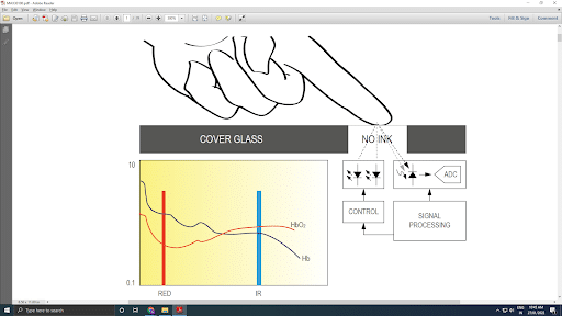
It turns out oxygenated blood absorbs more infrared light and passes more red light, while deoxygenated blood absorbs red light and gives more infrared light.
This is the primary function of the MAX30100: it absorbs red light, passes more infrared light sources, and stores them in a buffer that can be read via an I2C communication protocol.
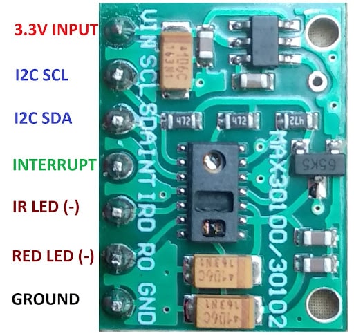
Pin Diagram of MAX30100 and MAX30102 Oximeter Module
MAX30100 and MAX30102 is a seven-pin heart rate and SpO2 measurement oximeter sensor module, which communicates through I2C. The description of each pin is mentioned below.
| PIN | FUNCTION |
| VIN | 3.3V DC Input Voltage |
| SCL | I2C Serial Clock Input |
| SDA | I2C Bidirectional Serial Data |
| INT | Active Low Interrupt (Open Drain) |
| IRD | Cathode connection for IR LED and LED Driver (Leave floating in the circuit) |
| R0 | Cathode connection for Red LED and LED Driver (Leave floating in the circuit) |
| GND | Analog Ground |
What is the difference between MAX30100 and MAX30102?
Storage:
MAX30102 is capable of storing digital output as 32-deep FIFO data within the IC, while MAX30100 has 16-deep FIFO. 32-bits FIFO makes MAX30102 faster than MAX30100.
ADC resolution:
18 bit ADC resolution of MAX30102 makes it more sensitive to changes in IR voltages, while MAX30100 has 16 bits resolution.
LED Pulse Width:
MAX30102 LED pulse width can be programmed from 69µs to 411µs, while MAX30100 can be programmed from 200µs to 1.6ms. A narrow pulse width of MAX30102 allows higher accuracy for SpO2 and Heart Rate measurement and also reduces power consumption.
Wiring MAX30100 pulse oximeter with Arduino UNO
Now, I will give you the step-by-step instructions for interfacing MAX30100 or MAX30102 with Arduino UNO with LCD to display the result of heart rate and SpO2.
How do you make an Arduino pulse sensor?
Step 1: Interface MAX30100 or MAX30102 to Arduino UNO
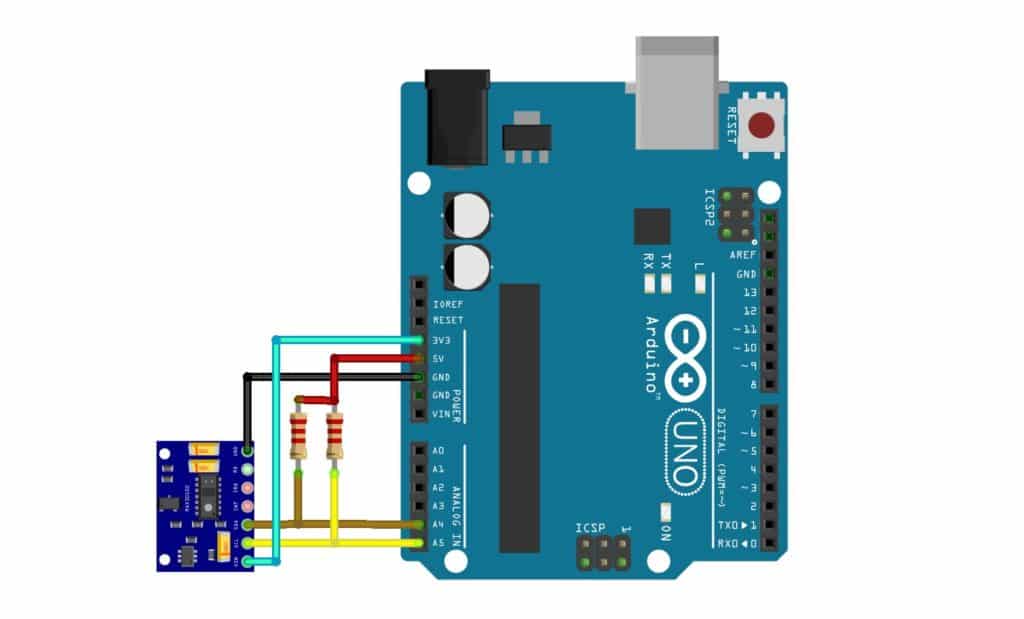
First, You should connect the MAX30100 or MAX30102 module to Arduino UNO. For that, you need to connect power supply pins and the I2C pins of IC to Arduino.
| MAX30100 Pin | Arduino UNO Pin |
| VIN | 3.3V |
| SCL | A5 (SCL) and pull up with 2.2 K to 5V |
| SDA | A4 (SDA) and pull up with 2.2 K to 5V |
| GND | GND |
If you are using Arduino UNO and your sensor MAX30100 or MAX30102 is not working with it, follow this procedure.
As Arduino UNO pins are working on 5V logic and MAX30100 pins are at 3.3V, you need to pull up SCL and SDA connection. You can use a 2.2K to 4.7K resistor on SCL and SDA lines and connect it to +5V.
Step 2: Interface 16×2 LCD To Arduino UNO
I am using a parallel 16×2 LCD, which works on 5V logic. As mentioned in the table below, you need to connect data pins, RS, and Enable LCD pins to Arduino UNO.
| 16×2 LCD Pin | Arduino UNO Pin |
| RS | Digital Pin 8 |
| E | Digital Pin 9 |
| D4 | Digital Pin 10 |
| D5 | Digital Pin 11 |
| D6 | Digital Pin 12 |
| D7 | Digital Pin 13 |
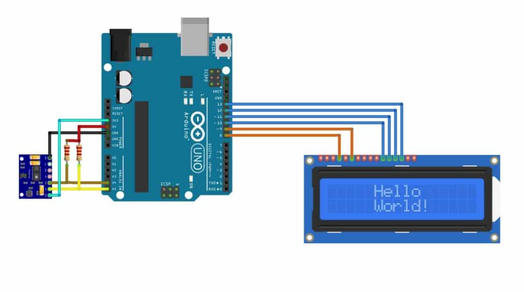
For more details, regarding the 16×2 LCD display wiring and control have a look at our tutorial on How to use a 16×2 character LCD with Arduino.
Step 3: Power Supply To 16×2 LCD
To provide power supply to 16×2 LCD, you need to connect VSS, RW, and K of LCD to common ground. Then, connect VDD to +5V, A to +5V with a 220-ohm resistor.
To vary the contrast of a 16×2 LCD, connect V0 to the single terminal of the 10K potentiometer and the remaining two terminals of the potentiometer to GND and +5V. You can vary the contrast by varying the potentiometer.
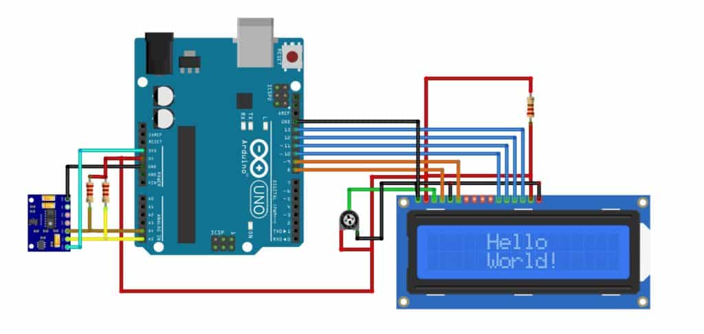
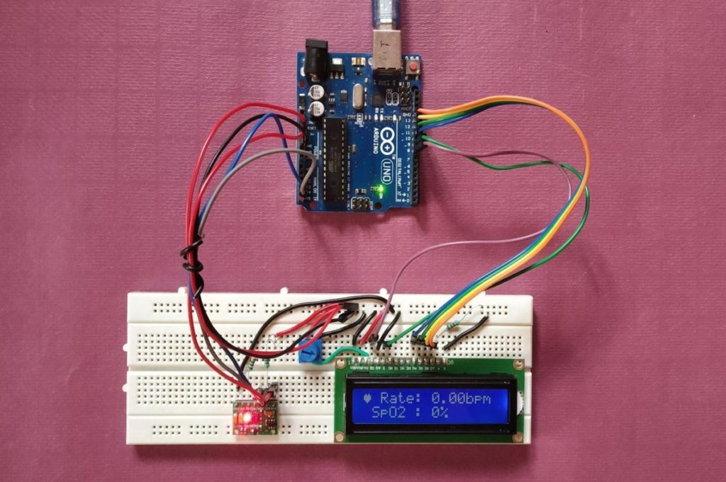
After all steps, your connection will look like the image below.
Installing the required Arduino libraries
To use MAX30100 or MAX30102 with Arduino IDE, you can use an already built library from MAX30100lib.
Follow the below-mentioned steps to install the MAX30100 library in Arduino IDE.
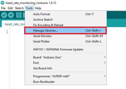
Step 1: Open Library Manager in Arduino IDE
Go to the Tools > Manage Libraries (Ctrl + Shift + I on Windows) to open the library manager in Arduino IDE.
Step 2: Search and Install MAX30100 Library
Now, in the search box, type “MAX30100” and you can see the different results for your search.
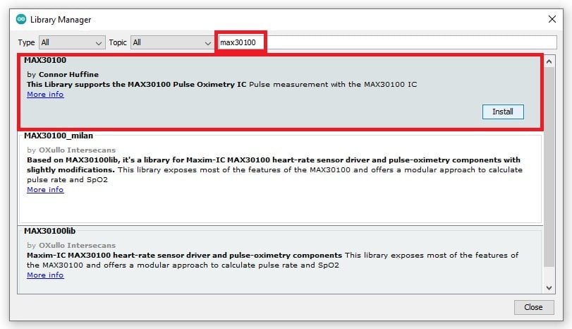
You can also install MAX30100 by Connor Huffine or MAX30100lib by OXullo Intersecans.
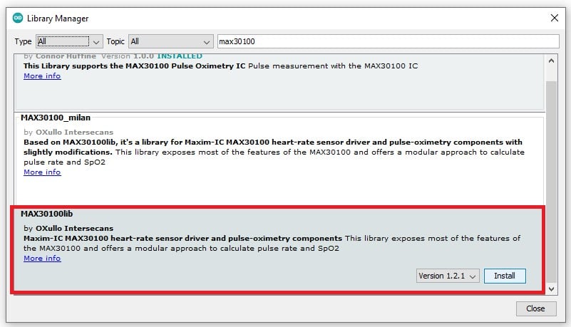
You need to click on Install to install the library in Arduino IDE. That’s it, and you have successfully installed the library for heart rate sensor MAX30100 in your Arduino IDE.
Arduino Code for Heart Rate Monitoring
The following code allows you to measure the heart rate in bpm and SpO2 in percentage using MAX30100 or MAX30102 pulse oximetry sensor. You can see the results on a serial monitor and a 16×2 LCD.
You can copy the code by clicking on the button in the top right corner of the code field and uploading it to your Arduino UNO board using Arduino IDE.
#include "Wire.h"
#include "MAX30100_PulseOximeter.h"
#include "LiquidCrystal.h"

#define UPDATE_TIME   1000

// variables and pin defination
const int rs = 8, en = 9, d4 = 10, d5 = 11, d6 = 12, d7 = 13;
byte heart [8] = {0b00000, 0b01010, 0b11111, 0b11111, 0b11111, 0b01110, 0b00100, 0b00000};
uint32_t previous_update_time = 0;

LiquidCrystal lcd(rs, en, d4, d5, d6, d7);
PulseOximeter pulse;

void on_pulse_detected()
{
  Serial.println("Pulse Detected!");
}

void setup() {
  Serial.begin(115200);
  Serial.print("Initializing Pulse Oximeter..");

  lcd.createChar(2, heart);
  lcd.begin(16, 2);
  lcd.clear();
  lcd.setCursor(2, 0);
  lcd.print("Initializing");
  lcd.setCursor(1, 1);
  lcd.print("Pulse Oximeter");

  delay(3000);

  if (!pulse.begin()) {
    Serial.println("Sensor begin Failed");
  } else {
    Serial.println("Sensor begin Success");
  }
  //set current
  pulse.setIRLedCurrent(MAX30100_LED_CURR_7_6MA);

  // for the pulse detection
  pulse.setOnBeatDetectedCallback(on_pulse_detected);
}

void loop() {
  pulse.update();

  if (millis() - previous_update_time > UPDATE_TIME) {

    // Display Result on LCD
    lcd.clear();
    lcd.setCursor(0, 0);
    lcd.write((uint8_t)2);
    lcd.print(" Rate:");
    lcd.print(pulse.getHeartRate());
    lcd.print("bpm");
    lcd.setCursor(0, 1);
    lcd.print(" SpO2 :");
    lcd.print(pulse.getSpO2());
    lcd.print("%");
    previous_update_time = millis();

    // Display Result on Serial Monitor
    Serial.print("Heart ❤ Rate:");
    Serial.print(pulse.getHeartRate());
    Serial.println("bpm");
    Serial.print(" SpO2 Level  :");
    Serial.print(pulse.getSpO2());
    Serial.println("%");
    previous_update_time = millis();
  }
}
How The Code Works
First, I have included the necessary header files for MAX30100 and 16×2 LCD. As MAX30100 uses the I2C communication protocol, you need to add Wire.h in your code.
#include "Wire.h"
#include "MAX30100_PulseOximeter.h"
#include "LiquidCrystal.h"
In void setup(), I have initialized the Serial Communication with a baud rate of 115200, So when you open the Serial Monitor on Arduino IDE, make sure that you set the baud rate as 115200.
Then, I have written a test condition for MAX30100 or MAX30102 IC.
if (!pulse.begin()) {
    Serial.println("Sensor begin Failed");
  } else {
    Serial.println("Sensor begin Success");
  }
}
If it is successfully initialized, then you will see “Sensor begin Success” on the serial terminal; otherwise, it will display “Sensor begin Failed” wait for infinite time in for loop.
Now, you can set the current through the LED. By default, the current through the LED is 50mA. I have set the current through the IR LED as 7.6mA.
pulse.setIRLedCurrent(MAX30100_LED_CURR_7_6MA);
You can set different currents for IR LED, and a higher current will allow deeper penetration through the skin. Below is the list of different current settings that you can apply in the code.
MAX30100_LED_CURR_0MA
MAX30100_LED_CURR_4_4MA
MAX30100_LED_CURR_7_6MA
MAX30100_LED_CURR_11MA
MAX30100_LED_CURR_14_2MA
MAX30100_LED_CURR_17_4MA
MAX30100_LED_CURR_20_8MA
MAX30100_LED_CURR_24MA
MAX30100_LED_CURR_27_1MA
MAX30100_LED_CURR_30_6MA
MAX30100_LED_CURR_33_8MA
MAX30100_LED_CURR_37MA
MAX30100_LED_CURR_40_2MA
MAX30100_LED_CURR_43_6MA
MAX30100_LED_CURR_46_8MA
MAX30100_LED_CURR_50MA
How do you measure heart rate with a sensor?
You can detect the pulse from the sensor by using the setOnBeatDetectedCallback function, which will call the on_pulse_detected function and print the “Pulse Detected!” message on the serial monitor.
pulse.setOnBeatDetectedCallback(on_pulse_detected);
void on_pulse_detected()
{
  Serial.println("Pulse Detected!");
}
In infinite void loop (), function pulse.update() updates the sensor reading. Time required to call pulse.update() function in the infinite loop should be less than 10 ms.
In the end, it will print the heart rate in bpm and SpO2 in percentage on a serial monitor and LCD every second. You can adjust the interval by changing the UPDATE_TIME value.
How does Arduino measure the heart rate?
if (millis() - previous_update_time > UPDATE_TIME) {
    //Display Result on LCD
    lcd.clear();
    lcd.setCursor(0, 0);
    lcd.write((uint8_t)2);
    lcd.print(" Rate:");
    lcd.print(pulse.getHeartRate());
    lcd.print("bpm");
    lcd.setCursor(0, 1);
    lcd.print(" SpO2 :");
    lcd.print(pulse.getSpO2());
    lcd.print("%");
    previous_update_time = millis();

    //Display Result on Serial Monitor
    Serial.print("Heart ❤ Rate:");
    Serial.print(pulse.getHeartRate());
    Serial.println("bpm");
    Serial.print(" SpO2 Level  :");
    Serial.print(pulse.getSpO2());
    Serial.println("%");
    previous_update_time = millis();
  }
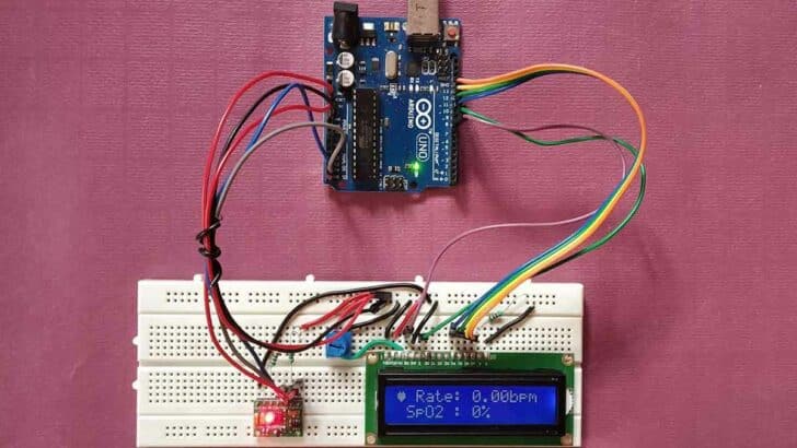
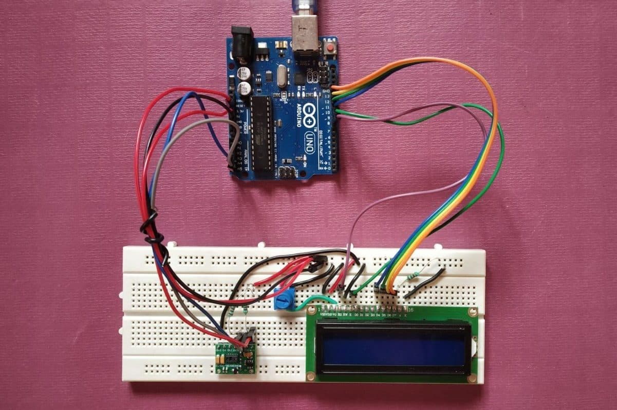
Finally, once you upload the code in Arduino UNO, the Red LED on the sensor will be turned ON, and the default value will be displayed on LCD, as shown below.
Video Demonstration of Heart Rate Monitoring System
Important Points
- The glass on the sensor should be clean and, don’t apply any INK over it.
- Put your finger in the correct place, over IR and Red LED, otherwise the sensor may generate incorrect results.
- Don’t move your finger; wait for the sensor to get initialized.
Conclusion
After this tutorial, you can develop your own Heart Rate Monitoring System using MAX30100 or MAX30102 and Arduino UNO.
I hope you found this tutorial informative. If you did, please share it with a friend who likes electronics and making things!
I would love to know what project you plan on building or have already made with the Arduino. If you have any questions or suggestions, or if you think things are missing in this tutorial, please leave a comment below.
Links
Here some links to similar projects:
- Interfacing MAX30100 Heart Rate Monitor With Arduino
- How to Use the MAX30100 as Arduino Heart Rate Sensor
- Interfacing MAX30100 Pulse Oximeter
- How to Use MAX30100 Arduino as Heart Rate Sensor
- Interface MAX30100 Pulse Oximeter Sensor with Arduino
- Oximeter And Hearth-Rate Sensor with Arduino
- Interfacing MAX30100 Pulse Oximeter Sensor with Arduino

Hiren is a professional Embedded Engineer with a Master’s Degree
in Electronics and Communication Engineering. He is proficient in C and
C++ and enjoys building DIY projects on Arduino, ESP32, PIC32, STM32 & Raspberry PI boards.