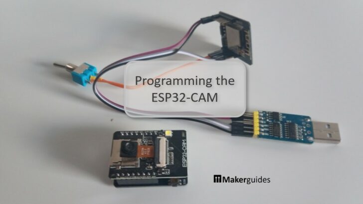
In this article you will learn the programming of the ESP32-CAM module. The ESP32 Camera modules are comparatively cheap and very nice to build simple surveillance or monitoring systems. For instance, automatically taking pictures of animals at night in your garden or announcing visitors at your front door via webcam, are common use cases.
However, actually uploading and running programs on the common EPS32-CAM development boards is a bit tricky. In this article we have a look at different methods to program and troubleshoot an ESP32-CAM board.
Required Parts
Below you will find the components required to build the project. Some of the parts such as USB cable, micro SD Card, or SD Card reader you may already have. No need to buy it then, none of those parts is special for this project. Though, the SD card should be not larger than 16 GB.
If you don’t have an FTDI USB-TTL Adapter, then that is definitely something you want. Sooner or later you will need one if you keep tinkering with ESP32 microcontrollers. The one listed is a simple one but will be sufficient for most cases.
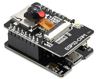
ESP32-CAM with USB-TTL Shield
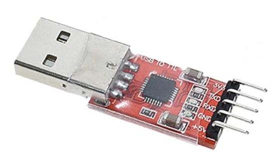
FTDI USB-TTL Adapter
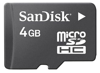
MicroSD Card 4GB
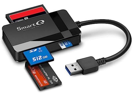
SD Card Reader
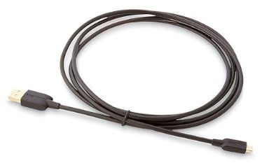
USB Data Cable
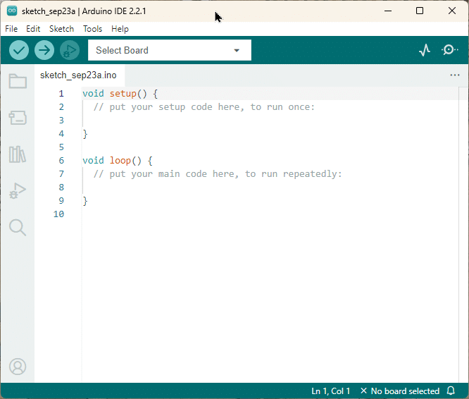
Arduino IDE
Makerguides.com is a participant in the Amazon Services LLC Associates Program, an affiliate advertising program designed to provide a means for sites to earn advertising fees by advertising and linking to products on Amazon.com. As an Amazon Associate we earn from qualifying purchases.
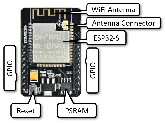
Basics of the ESP32-CAM Development Board
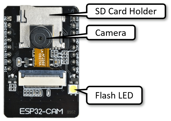
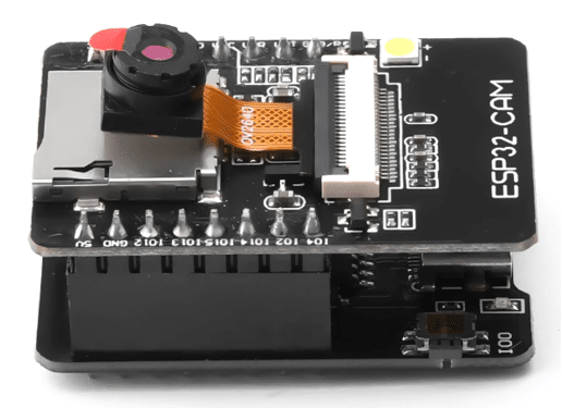
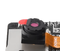
The ESP32-CAM Development Board is a compact module that combines an ESP32-S chip, a camera, a built-in flash, and a microSD card slot. The board has integrated Wi-Fi and Bluetooth and supports a OV2640 or OV7670 camera with up to 2 megapixels resolution.
You can find the detailed specification of the board below. Note that in the example code we will refer to the original AI-Thinker model of the ESP32-CAM board but there are many clones with exactly the same specifications. They are programmed and used in the same way – including the one we listed under Required Parts.
Features
- Ultra-small 802.11b/g/n Wi-Fi + BT/BLE SoC module.
- Low-power dual-core 32-bit CPU for application processors.
- Main frequency up to 240MHz, computing power up to 600 DMIPS.
- Built-in 520 KB SRAM, external 4M PSRAM.
- Supports interfaces such as UART/SPI/I2C/PWM/ADC/DAC.
- Support OV2640 and OV7670 cameras, built-in flash.
- Support image WiFi upload, support TF card.
- Support multiple sleep modes
- Support STA/AP/STA+AP working mode.
Specifications
- Size: 27*40.5*4.5(±0.2)mm
- SPI Flash: 32Mbit by default
- RAM: Internal 520KB + external 4M PSRAM
- BT: BT 4.2BR/EDR and BLE standards
- WiFi: 802.11 b/g/n/e/i
- Support interface: UARI, SPI, I2C, PWM
- Support TF card: 4G (up to 16GB usually works)
- IO port: 9
- Image output format: JPEG (only supported by OV2640), BMP, GRAYSCALE
- Antenna form: onboard antenna, gain 2dBi
- Security: WPA/WPA2/WPAS-Enterprise/WPS
- Power supply range: 5V
- Working temperature: -20 °C to 85 °C
Power consumption
- Without flash: 180mA@5V
- With flash at maximum brightness: 310Ma@5V
- Deep-sleep: 6mA@5V
- Modem-sleep: 20mA@5V
- Light-sleep: 6.7mA@5V
Pinout
The following picture shows the Pinout of the ESP32-CAM. Note that in theory the EPS32-CAM can run on 3.3V but unstable behavior and pictures with watermarks have been reported. The recommended power supply is therefore 5V @ 2A.
Also note that IO0 is connected to the camera XCLK pin and should be left floating (no connected) when running the ESP32. You should only pull IO0 down to GND, when uploading code. More about that later.
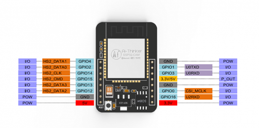
Compared to a standard ESP32 board the ESP32-CAM board has a much smaller number of available GPIO pins. This is, because most of the GPIO pins are used by the camera and the SD card reader. In addition, you should avoid using GPIO1, GPIO3 and GPIO0, since they are needed for programming the board.
The P_OUT pin is labelled as VCC on some boards. It is a power out pin that outputs 3.3V or 5V depending on a solder pad. You cannot use this pin to power the board! Use the 5V pin for that.
Finally, GPIO pins 2, 4, 12, 13, 14, and 15 are used by the SD Card reader. If you don’t use the SD Card reader they are available for GPIO. The built-in Flash LED is connected to GPIO 4, which causes the Flash LED to light up when the SD Card reader is used. You can use the following code to avoid this:
SD_MMC.begin("/sdcard", true)
You can find additional information regarding the pinout of the ESP32-CAM board at this RandomNerd tutorial: ESP32-CAM AI-Thinker Pinout Guide: GPIOs Usage Explained.
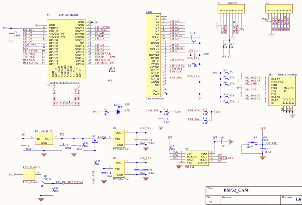
Schematics
If you need a detailed understanding of the internal wiring of the ESP32-CAM board have a look at the following schematics (source). Click on the picture to open or download the PDF with the full resolution schematics.
Installing the ESP32 Core
To program the ESP32-CAM, you will need the Arduino IDE with the ESP32 board support installed. Luckily, installing the ESP32 Core is very simple. Just start your Arduino IDE and follow the steps outlined below. If you have issues, you can find more detailed instructions in our tutorial How to Program ESP32 with Arduino IDE.
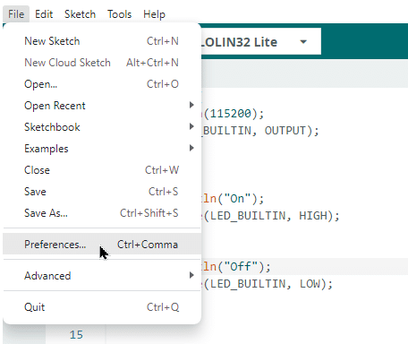
Additional boards manager URLs
First open the Preferences dialog by selecting “Preferences…” from the “File” menu:
This will open the Preferences dialog shown below. Under the Settings tab you will find an edit box at the bottom of the dialog that is labelled “Additional boards manager URLs“:
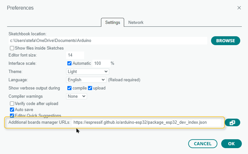
In this input field copy the following URL: “https://espressif.github.io/arduino-esp32/package_esp32_dev_index.json“
This will let the Arduino IDE know, where to find the ESP32 core libraries. Next we will actually install the ESP32 core libraries using the Boards Manager.
Boards Manager
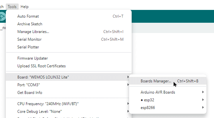
Open the Boards Manager via the Tools menu. In the screenshot below you can see that I have the “WEMOS LOLIN32 Lite” board selected. You will see a different board there but that is fine. Just select whatever board you see and click on “Boards Manager …”:
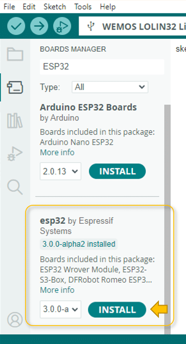
You will see the Boards Manager appearing in the left Sidebar. Enter “ESP32” in the search field at the top and you should see two types of ESP32 boards; the “Arduino ESP32 Boards” and the “esp32 by Espressif” boards. We want the esp32 libraries by Espressif. Click on the INSTALL button and wait until the download and install is complete.
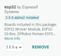
Once installed your Boards Manager should look like this, though the actual version (here 3.0.0-a) might differ.
In the next step, I show you how to select the ESP32 board you want to program.
Select the Board
To select a board go the Tools menu. Click on Board: “Arduino Uno”. Again you may see a different board from what is shown below. That is fine. Go to the submenu and you should see the “Arduino AVR Boards” and below the “esp32” (As you can see, I have also the esp8266 boards installed). Click on “esp32” and you will get a large list of available board.
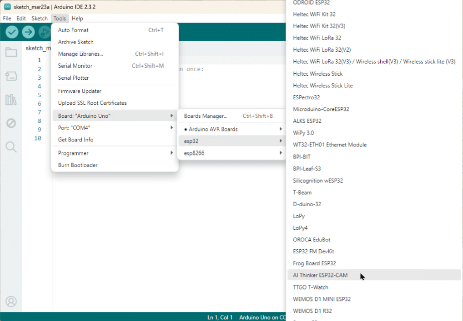
Find the AI Thinker ESP32-CAM board in the list and click on it.
Now you are ready to upload and run code on the ESP32-CAM board. I will show you two different ways to do this. You can use one of the Programming Shields that are often sold together with the ESP32-CAM module. Or you can use a separate and more universal FTDI programmer. We start with the Programming Shield first.
Upload code using a Programming Shield
If you want to program an ESP32 chip directly you need to use the serial UART interface. This is available via the U0TXD and UORXD pins you see in the Pinout. However, we want to program the ESP32 using the USB port of our computer (and the Arduino IDE). For this we need a USB to UART converter.
Programming Shield
Many develop boards with an ESP32 have an integrated chip (CH340) that does this USB to UART conversion but the ESP32-CAM module unfortunately has not. You therefore need a Programming Shield, such as depicted below, or an FTDI programmer, which we will discuss later.
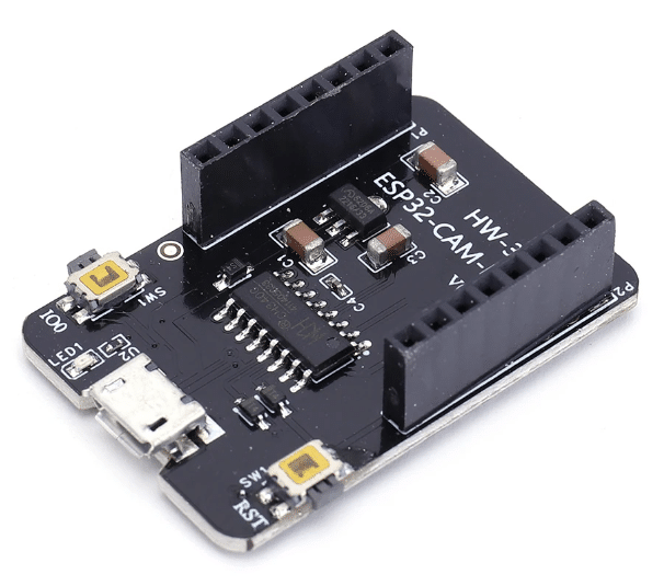
Just stack the ESP32-CAM module on top of the Programming Shield as shown below, connect a USB cable from Programming Shield to your computer, and you are ready for some programming.
Connecting the Programming Shield to the Computer
First make sure that the USB cable is properly connected and working. You should hear a pinging sound from your computer and a red LED on the Programming Shield should light up, when plugging in the USB cable. Next ensure that you have the AI Thinker ESP32-CAM board and the proper Serial Port selected. See the picture below.
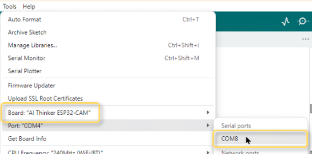
The Serial Port you see will probably different. It will depend on your computer and which USB port you use to connect to the ESP32-CAM.
Programming Mode
To upload a program to the ESP32-CAM you need to do the following:
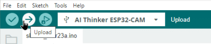
Start the upload via the upload button in the Arduino IDE:
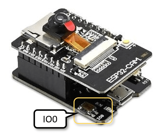
On the Programming Shield press and hold down the IO0 button on the side of the module:
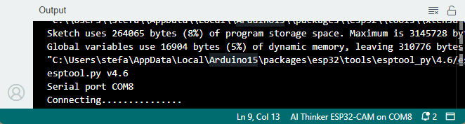
Wait until the text “Connecting …..” appears in the Output Panel:
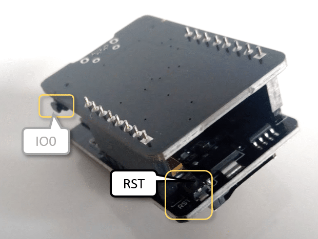
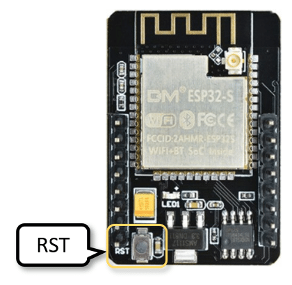
Then (while still holding down IO0) press and release the RST button (half a second) on the ESP32-CAM (not the Programming Shield). This button is at a really awkward position but the RST button on the Programming Shield didn’t work for me. The image below shows you the location of the RST button, that needs to be pressed.
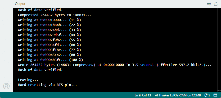
When the dots in the text “Connecting …..” stop appearing you can let go of the IO0 button as well. After that you should see the following text in the Output Panel appearing, indicating that the code is now uploading:
Running Mode
Once the text “Hard resetting via RTS pin…” appears in the Output Panel the upload is complete. You can then run the uploaded program by pressing the RST button on the ESP32-CAM module. As before, do not use the RST button on the Programming Shield and do not press the IO0 button.
You can use the following test code to try the upload.
Test code for ESP32-CAM with Programming Shield
This is a simple Blink program that lights up the Flash LED on the ESP32-CAM for 10 msec, then waits for 2 seconds and then repeats the cycle.
int flashPin = 4;

void setup() {
  pinMode(flashPin, OUTPUT);
}

void loop() {
  digitalWrite(flashPin, HIGH);
  delay(10);
  digitalWrite(flashPin, LOW);
  delay(2000);
}
If you see the LED flashing, you have successfully uploaded a program to the ESP32-CAM.
You may have noticed that uploading code to the ESP32-CAM is a really cumbersome procedure. You would expect the Programming Shield to automatically switch the ESP32 into programming mode, and you don’t need to press any buttons but that wasn’t working with either of the two Programming Shields, I tried.
Even then, the timing seems to be somewhat critical and the communication is brittle. I frequently had to try more than once to get a successful upload. Often unplugging and reconnecting the USB cable helped. Sometimes the upload started without me pressing any buttons after switching USB ports.
In the next section, I show you how to use an FTDI programmer, which makes the uploading of code a bit easier but still not fully automatic.
Upload code using an FTDI programmer
An FTDI Programmer or FTDI USB-TTL Adapter does the essentially same job as the Programming Shield for the ESP32-CAM. It converts USB signals to serial signals and allows you to program microcontrollers such as the Arduino and the ESP32 via the UART interface.
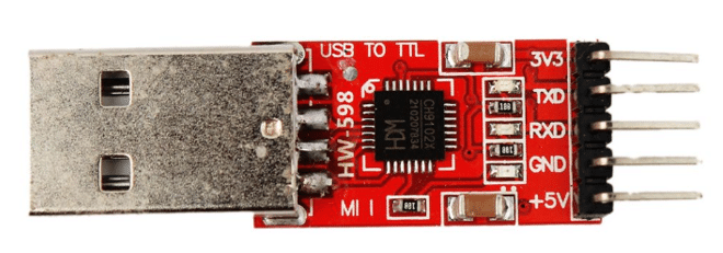
In contrast to the Programming Shield, the FTDI programmer is not for a specific board but can be used with all microcontrollers that support serial communication. While the FTDI Programmer is more flexible, it requires you to do the wiring between FTDI Programmer and microcontroller yourself. And this is what we will do in the following section.
Connecting the FTDI Programmer with ESP32-CAM
The following picture shows you how to connect the FTDI Programmer to the ESP32-CAM module. Note that we do not use the Programming Shield here.
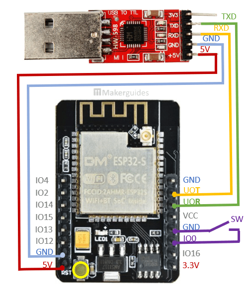
The connections are simple. Start by connecting GND of the Programmer with GND of the ESP32-CAM module (blue wire). Then do the same with the 5V power supply (red wire). Alternatively, you could use the 3.3V pins but there have been reports that the programming is then unstable.
Note that some FTDI Programmer have jumpers or switches to change from 3.3V to 5V. Watch out for that.
Next we connect the U0T (U0TXD) pin of the ESP32-CAM to the RXD pin of the Programmer (yellow wire). Similarly, U0R gets connected to TXD (green wire). With that the serial communication is established.
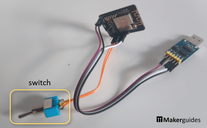
To switch the ESP32-CAM into programming mode the IO0 pin needs to be connected to ground (GND). But if you want to run the program, the IO0 pin needs to be left floating. I therefore connected a switch between IO0 and GND (purple wire) that allowed me to switch from programming to running mode an vice versa. See picture below:
Programming Mode
Programming using the FTDI Programmer is very similar to using the Programming Shield. Start by switching the ESP32-CAM module into programming mode by flipping the switch (IO0 connected to GND).
Then press the upload button in the Arduino IDE:
Wait until the text “Connecting …..” appears in the Serial monitor:
Then quickly press and release the RST button on the ESP32-CAM.
The dots after “Connecting …..” should stop appearing and you should see the uploading progress in the Output Panel:
Running Mode
Once the text “Hard resetting via RTS pin…” appears in the Output Panel the upload is complete. Flip the switch to change from programming mode to running mode and press the RST button on the ESP32-CAM to start the program.
You can use the same test code as shown above or try something a tiny bit more advanced as the following code.
Test code for ESP32-CAM with FTDI Programmer
This is essentially the same as a Blink program but we are slowly increasing the brightness of the Flash LED over 255 steps, then switching it off for a second and then repeat this cycle.
int flashPin = 4;

void setup() {
  pinMode(flashPin, OUTPUT);
}

void loop() {
  for (int b = 0; b < 255; b++) {
    analogWrite(flashPin, b);
    delay(1);
  }
  analogWrite(flashPin, 0);
  delay(1000);
}
Since the programming remains cumbersome (even with the FTDI Programmer), you want to test the function of SD Card and the Camera first before trying to run a more complex program. In the following two sections, I show you how to do this.
Testing the SD Card
According to the datasheet, the ESP32-CAM only supports 4GB microSD cards. However, 8GB and 16GB microSD card work generally fine. Larger cards need to be re-formatted with FAT32. Use the guiformat.exe software from ridgecrop to format bigger SD cards with FAT32.
The following test program creates a test file, writes some text to it, and reads the text from it. If that works then your SD Card works.
#include "SD_MMC.h"
#include "FS.h"
#include "LittleFS.h"

int flashPin = 4;

void setup() {
  Serial.begin(115200);
  SD_MMC.begin();
  LittleFS.begin(true);

  File file = LittleFS.open("/test.txt", FILE_WRITE);
  file.print("*** Test successful ***");
  file.close();

  file = LittleFS.open("/test.txt");
  while (file.available()) {
    Serial.write(file.read());
  }
  file.close();

  pinMode(flashPin, OUTPUT);
  analogWrite(flashPin, 0);
}

void loop() {
}
Here a more detailed explanation of the code.
Libraries and Initialization
We start by including the necessary libraries for SD card and file system operations: SD_MMC.h, FS.h, and LittleFS.h.
#include "SD_MMC.h"
#include "FS.h"
#include "LittleFS.h"
We also define a variable flashPin to represent the pin connected to the flash LED.
int flashPin = 4;
Setup Function
In the setup() function, we initialize the serial communication at a baud rate of 115200.
void setup() {
  Serial.begin(115200);
We then initialize the SD card and LittleFS file system. Calling LittleFS.begin with true ensures the file system for LittleFS is created. You usually need to do that only once but it doesn’t do any harm to call the function this way every time.
  SD_MMC.begin();
  LittleFS.begin(true);
Next, we create a file named test.txt in write mode, write a test message into it, and close the file.
  File file = LittleFS.open("/test.txt", FILE_WRITE);
  file.print("*** Test successful ***");
  file.close();
We reopen the file in read mode, read its contents character by character, and print them to the serial monitor.
  file = LittleFS.open("/test.txt");
  while (file.available()) {
    Serial.write(file.read());
  }
  file.close();
Finally, we set the flashPin as an output pin and turn off the Flash LED by setting its PWM value to 0. I do this, since writing to the SD Card automatically switches on the Flash LED, which is annoying. The test code works fine without these two lines but I didn’t like the Flash in my eyes every time I ran the test.
  pinMode(flashPin, OUTPUT);
  analogWrite(flashPin, 0);
Loop Function
The loop() function is left empty, since everything happens in the setup function. To rerun the program you need to reset the ESP32-CAM.
void loop() {
}
Output in Serial Monitor
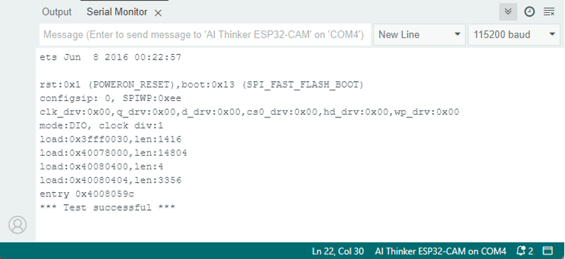
If everything works correctly, you should see the following lines in the Serial Monitor. Note the last line with “*** Test successful ***”, which proofs that we could write to and read from the SD Card.
Other Tests
Alternatively you can also run the more complex test that comes with ESP32 library. It has additional debugging output, which might be useful. You can find the sketch SDMMC_Test.ino here. The same code is available via the Sketch examples: File -> Examples -> Examples for AI-Thinker ESP32-CAM -> SDMMC -> SDMMC_Test.
Testing the Camera
After the SD Card we want to test the function of the camera. The below code is a simplified version of more complex programs. Every time the ESP32-CAM starts (reset button is pressed), it takes a picture and stores it on the SD card.
This code is specific for the AI-Thinker model but will work most other ESP32 based camera boards well, provided they have PSRAM (see model definitions here). You just need to replace the pin definitions based on your model.
#include "esp_camera.h"
#include "soc/rtc_cntl_reg.h"
#include "SD_MMC.h"
#include "EEPROM.h"

// CAMERA_MODEL_AI_THINKER
#define PWDN_GPIO_NUM 32
#define RESET_GPIO_NUM -1
#define XCLK_GPIO_NUM 0
#define SIOD_GPIO_NUM 26
#define SIOC_GPIO_NUM 27
#define Y9_GPIO_NUM 35
#define Y8_GPIO_NUM 34
#define Y7_GPIO_NUM 39
#define Y6_GPIO_NUM 36
#define Y5_GPIO_NUM 21
#define Y4_GPIO_NUM 19
#define Y3_GPIO_NUM 18
#define Y2_GPIO_NUM 5
#define VSYNC_GPIO_NUM 25
#define HREF_GPIO_NUM 23
#define PCLK_GPIO_NUM 22

void configCamera() {
  camera_config_t config;
  config.ledc_channel = LEDC_CHANNEL_0;
  config.ledc_timer = LEDC_TIMER_0;
  config.pin_d0 = Y2_GPIO_NUM;
  config.pin_d1 = Y3_GPIO_NUM;
  config.pin_d2 = Y4_GPIO_NUM;
  config.pin_d3 = Y5_GPIO_NUM;
  config.pin_d4 = Y6_GPIO_NUM;
  config.pin_d5 = Y7_GPIO_NUM;
  config.pin_d6 = Y8_GPIO_NUM;
  config.pin_d7 = Y9_GPIO_NUM;
  config.pin_xclk = XCLK_GPIO_NUM;
  config.pin_pclk = PCLK_GPIO_NUM;
  config.pin_vsync = VSYNC_GPIO_NUM;
  config.pin_href = HREF_GPIO_NUM;
  config.pin_sscb_sda = SIOD_GPIO_NUM;
  config.pin_sscb_scl = SIOC_GPIO_NUM;
  config.pin_pwdn = PWDN_GPIO_NUM;
  config.pin_reset = RESET_GPIO_NUM;
  config.xclk_freq_hz = 20000000;
  config.pixel_format = PIXFORMAT_JPEG;
  config.frame_size = FRAMESIZE_UXGA;
  config.jpeg_quality = 10;
  config.fb_count = 2;
  esp_err_t err = esp_camera_init(&config);

  sensor_t* s = esp_camera_sensor_get();
  s->set_brightness(s, 0);
  s->set_contrast(s, 0);
  s->set_saturation(s, 0);
  s->set_special_effect(s, 0);
  s->set_whitebal(s, 1);
  s->set_awb_gain(s, 1);
  s->set_wb_mode(s, 0);
  s->set_exposure_ctrl(s, 1);
  s->set_aec2(s, 0);
  s->set_ae_level(s, 0);
  s->set_aec_value(s, 300);
  s->set_gain_ctrl(s, 1);
  s->set_agc_gain(s, 0);
  s->set_gainceiling(s, (gainceiling_t)0);
  s->set_bpc(s, 0);
  s->set_wpc(s, 1);
  s->set_raw_gma(s, 1);
  s->set_lenc(s, 1);
  s->set_hmirror(s, 0);
  s->set_vflip(s, 0);
  s->set_dcw(s, 1);
  s->set_colorbar(s, 0);
}

unsigned int incCounter() {
  unsigned int cnt = 0;
  int adr = 0;
  EEPROM.get(adr, cnt);
  EEPROM.put(adr, cnt + 1);
  EEPROM.commit();
  return cnt;
}

void skipPictures(int n) {
  for(int i=0; i<n; i++) {
    camera_fb_t* fb = esp_camera_fb_get();
    esp_camera_fb_return(fb);
  }
}

void takePicture() {
  camera_fb_t* fb = esp_camera_fb_get();
  unsigned int cnt = incCounter();
  String path = "/pic" + String(cnt) + ".jpg";
  Serial.println(path);
  File file = SD_MMC.open(path.c_str(), FILE_WRITE);
  file.write(fb->buf, fb->len);
  file.close();
  esp_camera_fb_return(fb);
}

void setup() {
  WRITE_PERI_REG(RTC_CNTL_BROWN_OUT_REG, 0);
  Serial.begin(115200);
  SD_MMC.begin();
  EEPROM.begin(16);
  configCamera();
  skipPictures(n);
  takePicture();
  esp_deep_sleep_start();
}

void loop() {
}
This code is a good starting point for more advanced use cases. For instance, if you want to take a picture when a motion or light sensor is triggered. Or if you want to take pictures in certain time intervals. In the following, a bit more detail on how this code works.
Constants and Libraries
Firstly, we include necessary libraries such as esp_camera.h, soc/rtc_cntl_reg.h, SD_MMC.h, and EEPROM.h. These libraries provide functionalities for camera configuration, SD card operations, and EEPROM usage.
#include "esp_camera.h"
#include "soc/rtc_cntl_reg.h"
#include "SD_MMC.h"
#include "EEPROM.h"
Camera Configuration
The configCamera() function sets up the camera configuration parameters such as LEDC channel, pins for data lines (D0-D7), XCLK, PCLK, VSYNC, HREF, SCCB SDA, SCCB SCL, PWDN, RESET, and various camera settings like pixel format, frame size, JPEG quality, etc.
void configCamera() {
  camera_config_t config;
  config.ledc_channel = LEDC_CHANNEL_0;
  config.ledc_timer = LEDC_TIMER_0;
  config.pin_d0 = Y2_GPIO_NUM;
  config.pin_d1 = Y3_GPIO_NUM;
  ...

  sensor_t* s = esp_camera_sensor_get();
  s->set_brightness(s, 0);
  s->set_contrast(s, 0);
  s->set_saturation(s, 0);
  ...
}
As mentioned, depending on the camera type the pin definitions may change. Also if you are not happy with the quality of the pictures, there are many parameters you can play with.
Counter Increment Function
The incCounter() function reads and increments a counter value stored in EEPROM memory. It retrieves the current count, increments it, writes it back to EEPROM, and returns the previous count.
unsigned int incCounter() {
  unsigned int cnt = 0;
  int adr = 0;
  EEPROM.get(adr, cnt);
  EEPROM.put(adr, cnt + 1);
  EEPROM.commit();
  return cnt;
}
This ensures that we have a running counter for the pictures taken, despite resetting the EPS32-CAM, when we take a picture. This counter is also utilized to create unique filenames for the image files we store on the SD card.
If you want to reset the counter, you could upload and run the following code:
#include "EEPROM.h"

void setup() {
  EEPROM.begin(512);
  unsigned int cnt = 0;
  int adr = 0;
  EEPROM.put(adr, cnt);
  EEPROM.commit();
}

void loop() {
}
Skip Pictures
The SkipPictures(n) function captures n images and throws them away. The reason why we are doing this is the following: The camera has several automatic functions integrated, for instance automatic white balance and others that take some time and several image frames to adjust to the environment. After a restart from deep sleep, we therefore need to give the camera a bit of time to adjust.
void skipPictures(int n) {
  for(int i=0; i<n; i++) {
    camera_fb_t* fb = esp_camera_fb_get();
    esp_camera_fb_return(fb);
  }
}
If you take the first image after a restart you will find that it is of horrible quality. Typically with a strong blue tint, or to very dark or bright. However, after skipping the first few frames you mostly (but not always) get pictures of good quality.
You could also try to disable automatic white balance and other automatic functions in the camera settings, but then you will need to have a fairly stable environment to be able to tune the other settings. Otherwise, it will be difficult to get good quality pictures.
Image Capture and Storage
The takePicture() function captures an image using the camera and saves it to an SD card. It retrieves a camera frame buffer, increments the counter, creates a unique file path for the image, writes the image data to the file, and releases the frame buffer.
void takePicture() {
  camera_fb_t* fb = esp_camera_fb_get();
  unsigned int cnt = incCounter();
  String path = "/pic" + String(cnt) + ".jpg";
  Serial.println(path);
  File file = SD_MMC.open(path.c_str(), FILE_WRITE);
  file.write(fb->buf, fb->len);
  file.close();
  esp_camera_fb_return(fb);
}
Note that we use the aforementioned counter to create file path names. If you don’t like the file names, then this is the place to change it.
Setup Function
In the setup() function, we first disable the brownout detector. The ESP32-CAM is overly eager to throw brownout errors, if the power supply deliver low current during start up. Calling WRITE_PERI_REG(RTC_CNTL_BROWN_OUT_REG, 0) avoids this problem.
Then we initialize serial communication, start the SD card, begin EEPROM, configure the camera, capture an image, and initiate deep sleep mode. This means, every time the ESP32-CAM starts or resets, a new picture is taken and stored on the SD card.
void setup() {
  WRITE_PERI_REG(RTC_CNTL_BROWN_OUT_REG, 0);
  Serial.begin(115200);
  SD_MMC.begin();
  EEPROM.begin(512);
  configCamera();
  takePicture();
  esp_deep_sleep_start();
}
Loop Function
The loop() function is empty. Everything happens during setup and only a single picture is taken, after which the board goes into deep sleep and waits for a restart.
Camera Web Server Example
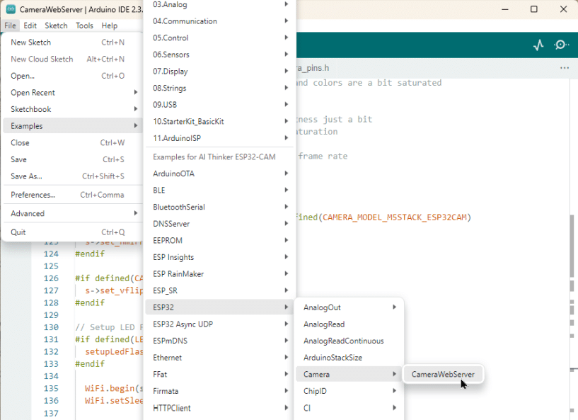
If you want a to use a test that includes using the WiFi capabilities of the ESP32 then the CameraWebServer example is nice. You can find it under File -> Examples -> Examples for AI-Thinker ESP32-CAM -> ESP32 -> Camera -> CameraWebServer.
You will have to change the code in CameraWebServer.ino slightly. First, you need to define the camera model you are using. Make sure only the model you have is defined!
// ===================
// Select camera model
// ===================
//#define CAMERA_MODEL_WROVER_KIT // Has PSRAM
//#define CAMERA_MODEL_ESP_EYE // Has PSRAM
...
//#define CAMERA_MODEL_M5STACK_UNITCAM // No PSRAM
#define CAMERA_MODEL_AI_THINKER // Has PSRAM
//#define CAMERA_MODEL_TTGO_T_JOURNAL // No PSRAM
//#define CAMERA_MODEL_XIAO_ESP32S3 // Has PSRAM
Next, you have to enter the WiFi credentials of your home WiFi network:
// ===========================
// Enter your WiFi credentials
// ===========================
const char* ssid = "**********";
const char* password = "**********";
After uploading the code and resetting the ESP32-Cam you should see the following text in the Serial Monitor:
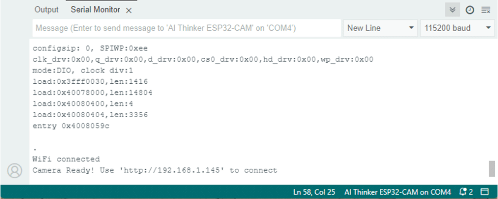
CameraWebServerNote the last line, which provides you with the URL (IP address) the WebServer is running at. Copy and paste this URL into the address bar of your browser and you should see the following website, that streams camera pictures from your ESP32-CAM to your Web browser.
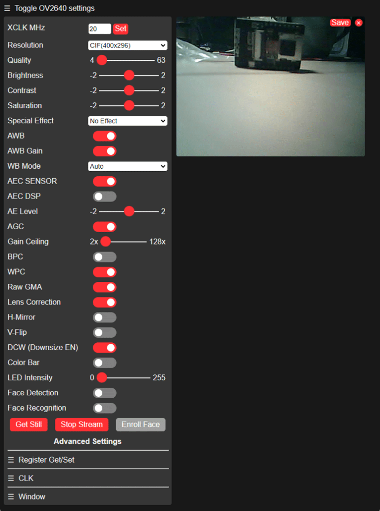
CameraWebServer in Web browserAnd that’s it! This should give you enough information and examples to get started with the ESP32-CAM module.
Summary
The ESP32-CAM module is a nice and capable board once you’ve got it running. However, getting code to reliably upload to the module is cumbersome. I often had to try several times and unplug the USB cable to get it working. Actually, the most reliable method was the following:
- Unplug USB cable
- Switch board into Programming mode
- Plug in the USB cable
- Start the Upload in Arduino IDE
That worked reliably and did not require pressing the RST button during upload. To then run the ESP32-CAM I just had to disable programming mode and press reset. No unplugging of the USB cable was need for that. Only for uploading a new program I had to unplug the board and go through the steps again
If you have difficulties with your ESP32-CAM board, in below are some links with additional information and a list of frequently asked questions with answers.
Enjoy tinkering!
Links
Here some links I found useful to get started with the ESP32-CAM:
- Getting Started With ESP32-CAM
- How to Program / Upload Code to ESP32-CAM AI-Thinker (Arduino IDE)
- ESP32-CAM Troubleshooting Guide: Most Common Problems Fixed
- ESP32-CAM AI-Thinker Pinout Guide: GPIOs Usage Explained
- ESP32-CAM Take Photo and Save to MicroSD Card
- Camera Pin Definitions
- Supported Camera Models
Frequently Asked Questions
And here are some common questions and solutions to help you troubleshoot:
Q: Why is my ESP32-CAM not connecting to Wi-Fi?
A: Check if you have entered the correct SSID and password in your code. Ensure that the Wi-Fi network is within range and functioning properly.
Q: How can I improve the image quality of the camera?
A: Adjust the camera settings in your code to optimize the image quality. Experiment with different resolutions and frame rates to find the best configuration for your project.
Q: Why is my ESP32-CAM not capturing clear images?
A: Poor lighting conditions can affect image quality. Ensure proper lighting for the camera to capture clear images. Adjust camera settings in your code for optimal image quality. Also make sure you have removed the little lens protection foil.
Q: What should I do if my ESP32-CAM is not responding to commands from the serial monitor?
A: Check the serial communication settings in your code and ensure that the correct baud rate (115200) is set in both the code and the serial monitor. Verify the connections between the ESP32-CAM board and the computer.
Q: Why is my SD card not being detected?
A: Make sure the SD card is properly inserted into the slot and formatted correctly (FAT32). Check your code to ensure that the SD card initialization is done correctly. 4-16GB Cards should work fine. Higher capacity cards may cause issues.
Q: My ESP32-CAM is getting hot, is this normal?
A: It is normal for the ESP32-CAM to get warm during operation, but if it is excessively hot, check for any short circuits or power supply issues.
Q: How can I reduce the power consumption of the ESP32-CAM?
A: Disable unnecessary peripherals and optimize your code to minimize power consumption. Consider using sleep modes to conserve power when the board is not in use.
Q: Why are the images taken by the ESP32-CAM have a blue tint after a restart?
A: The camera has automatic functions, for instance automatic white balance that take some time and to adjust to the environment. Without that you will get blue-tinted or very dark or bright pictures. An easy way to avoid this to take several pictures after a restart and ignore them. See the skipPictures() function in the tutorial that does exactly that.
Q: Why is my ESP32-CAM not capturing images?
A: Check if the camera module is connected properly to the ESP32-CAM board. Ensure that the camera pins are correctly wired and that the camera module is supported by your code.
Q: How can I stream video from the ESP32-CAM?
A: Implement a streaming server on the ESP32-CAM using libraries like ESP32-CAM-Webserver to stream video over Wi-Fi. Ensure that your network can handle the video streaming bandwidth.
Q: Why is my ESP32-CAM not recognized by the Arduino IDE?
A: Ensure that you have installed the necessary ESP32 board support package in the Arduino IDE. Check your USB cable and port connections to ensure proper communication with the ESP32-CAM board.
Q: Why does my ESP32-CAM keep showing “Timed out waiting for packet header” during code upload?
A: This error can occur due to a slow or unstable USB connection. Try using a different USB cable or port, and ensure that the ESP32-CAM board is powered on and in bootloader mode before uploading the code.
Q: What should I do if my ESP32-CAM freezes during code upload?
A: Disconnect the USB cable, reset the ESP32-CAM board, and try uploading the code again. Ensure that your code is not causing the board to hang or crash during the upload process.
Q: Can I upload code to the ESP32-CAM wirelessly?
A: Yes, you can upload code wirelessly to the ESP32-CAM using OTA (Over-The-Air) programming. Implement OTA functionality in your code and follow the necessary steps to upload code without a USB connection.
Q: Why is my ESP32-CAM not entering bootloader mode for code upload?
A: Double-check the GPIO0 pin to GND connection on the ESP32-CAM board. Ensure that you are pressing the reset button at the right time to enter bootloader mode for code uploading.
Q: How can I resolve “A fatal error occurred: Failed to connect to ESP32: Timed out waiting for packet header” when uploading code?
A: This error can occur due to incorrect baud rate settings or a faulty USB cable. Try changing the baud rate in the Arduino IDE settings or using a different USB cable to establish a stable connection with the ESP32-CAM board.
Q: What steps should I take if I see “esptool.FatalError: Timed out waiting for packet header” when uploading code to the ESP32-CAM?
A: This error may indicate a communication timeout issue between the computer and the ESP32-CAM board. Check the USB cable, port, and board connections for any issues. Restart the IDE, reset the board, and try uploading the code again.
Stefan is a professional software developer and researcher. He has worked in robotics, bioinformatics, image/audio processing and education at Siemens, IBM and Google. He specializes in AI and machine learning and has a keen interest in DIY projects involving Arduino and 3D printing.