The CCS811 VO Sensor is an ultra-low power gas sensor that integrates a metal oxide gas sensor that detects a wide range of Volatile Organic Compounds (VOCs).
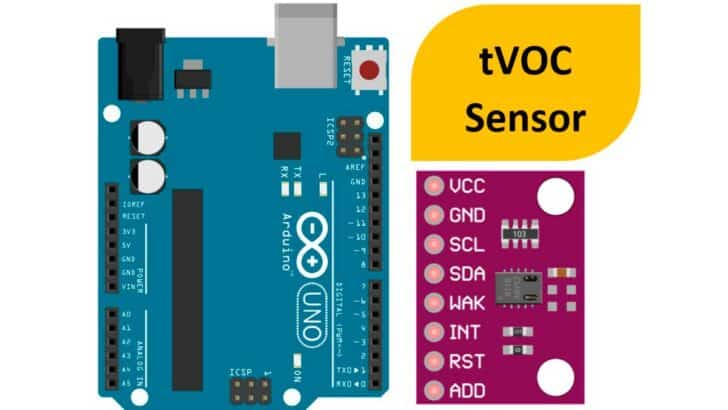
In this article, we will learn how to use a CCS811 VOC sensor with Arduino.
The CCS811 VO sensors are used in indoor air quality monitoring. The sensor communicates with an MCU using the I2C protocol.
The CCS811 incorporates a Microcontroller, an ADC, and an I2C interface.
It processes raw data and provides a reading for TVOC (Total Volatile Organic Compounds) or equivalent CO2.
In this article, you will find the basics of the CCS811 sensor, followed by the wiring connection diagram required to build a working project using Arduino UNO.
You will find example Arduino code and a collection of frequently asked questions about the VOC sensors.
Let’s get started!
Components Needed To Build Arduino And VCO Sensor Project
Hardware Components
- Dupont wire x 1 set
- Arduino USB cable (for powering Arduino and programming) x 1
Software
Makerguides.com is a participant in the Amazon Services LLC Associates Program, an affiliate advertising program designed to provide a means for sites to earn advertising fees by advertising and linking to products on Amazon.com.
Basics of The CCS811 TVOC Sensor
In this section, we will understand the features, specifications, and connection options available on the ultra-low power CCS811 total volatile organic compound sensor.
The CCS811 can provide VOC levels without host intervention, simplifying the hardware and software design.
The optimized low-power modes help you extend battery life in portable applications.
Applications of CCS811 Arduino VOC sensor
The applications of the VOC sensor, CCS811, are listed below
- Indoor air quality monitoring in smartphones
- VOC sensing in Home and Building Automation
- Wearables and accessories
The eCO2 and TVOC range of the sensor is listed in the table below
| Parameter | Output Range | Remarks |
| eCO2 | 400 PPM to 8192 PPM | Values outside this range to clipped |
| TVOC | 0 to 1187 PPB |
The Sensor module has one ADDR pin option which you can either connect to the ground or to the VCC. The ADDR pin will decide the I2C address as per the table below.
| ADDR Pin status | I2C Address (hex) | I2C Address (dec) |
| Low | 0x5A | 90 |
| High | 0x5B | 91 |
Functional block diagram of the VOC Sensor
The functional block diagram depicting the internal blocks of the VOC sensor is shown below.
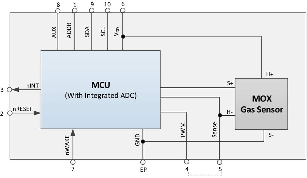
Pin Description
The CCS811 VOC sensor is a 10 pin IC with an exposed pad. Exposed pad must be connected to the ground for better thermal performance.
| Pin No. | Pin Name | Description |
| 1 | ADDR | – Single address select bit to allow alternate address to be selected. This helps you to connect two sensors one I2C line. – When ADDR is low the 7 bit I²C address is decimal 90 / hex 0x5A – When ADDR is high the 7 bit I²C address is decimal 91 / hex 0x5B. |
| 2 | nRESET | nRESET is an active low input and is pulled up to VDD by default. nRESET is optional but external 4.7KΩ pull-up and/or decoupling of the nRESET pin may be necessary to avoid erroneous noise-induced resets. |
| 3 | nINT | nINT is an active low optional output. It is pulled low by the CCS811 to indicate end of measurement or a set threshold value has been triggered. |
| 4 | PWM | Heater driver PWM output. Pins 4 and 5 must be connected together. |
| 5 | Sense | Heater current sense. Pins 4 and 5 must be connected together. |
| 6 | VDD | Supply voltage |
| 7 | nWAKE | nWAKE is an active low input and should be asserted by the host prior to an I²C transaction and held low throughout. |
| 8 | AUX | Optional AUX pin which can be used for ambient temperature sensing with an external NTC resistor. If not used, leave unconnected. |
| 9 | SDA | SDA pin is used for I²C data. Should be pulled up to VDD with a resistor |
| 10 | SCL | SCL pin is used for I²C clock. Should be pulled up to VDD with a resistor |
| EP | Exposed Pad | Connect to ground |
The sensor can work with a voltage in the range of 1.8 V to 3.6 V. The sensor consumes about 30 mA during operation and 19 uA during sleep mode.
The board has an onboard 5 V to 3.3 V converter. Hence you can use the board with Arduino UNO without any issues.
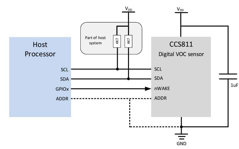
You can find the basic connection needed to complete the circuit in the image below.
The host can put the module to sleep using nWAKE pin.
Operation Modes of the CCS811 sensor
CCS811 sensor supports five different modes of operation. The different possible modes allow you to choose the best configuration for your specific application.
- Mode 0 – Idle, Low current mode of operation.
- Mode 1 – Constant Power mode, Measures IAQ every second.
- Mode 2 – Pulse heating mode and measurements are done every 10 seconds.
- Mode 3 – Measurements are done every hour.
- Mode 4 – Constant Power mode – Sensor measurement is done four times a second.
-> Read our guide about What You Can Build with Adruino.
Step-By-Step Instructions To Connect The VOC Sensor With Arduino UNO
In this section, we will build a project using Arduino UNO and the CCS811 VOC sensor.
The I2C lines of the CCS811 sensor pins are available to connect to the Arduino UNO.
Let’s get started with the hardware connections!
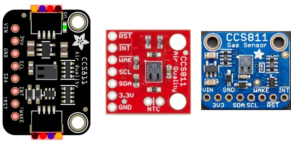
Below is the board we will use to complete the connections.
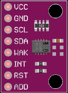
You might find several board variants, but the primary connection and the Arduino code remain the same.
We will connect the Arduino to the CCS811 VOC sensor in the coming sections.
How To Connect The CCS811 Sensor To The Arduino UNO?
Below is the step-by-step guide to complete the minimal connections needed to connect the Arduino and CCS811 VOC Sensor.
Step 1: Start with the GND connections.
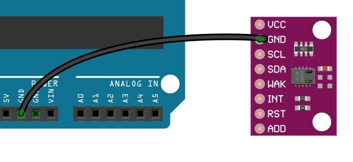
You can connect any GND pins available on the Arduino UNO board.
Connect the ground pin on the CCS811 sensor to the GND pin of the Arduino.
Always start with the ground connections. Connecting the GND pins first avoids accidental damage to the boards.
Step 2: Connect the I2C Clock Pin
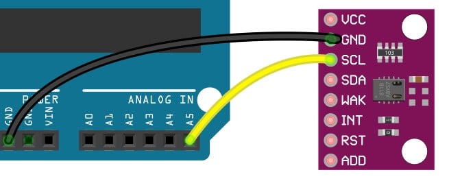
Connect the Arduino UNO’s A5 pin to the SCL pin of the Sensor.
The I2C clock pin of the Arduino is pin A5.
The I2C data line of pin A4 is SDA.
Step 3: Connect the I2C data pin
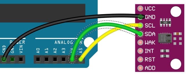
Connect the Arduino UNO’s A4 pin to the SDA pin of the Sensor.
The I2C clock pin of the Arduino is pin A5.
The I2C data line of pin A4 is SDA.
Step 4: Connect WAKE pin
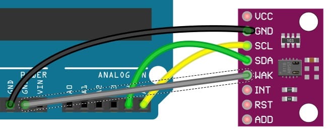
Connect the WAKE pin to the ground. If you connect the WAK pin to high voltage, you will put the CCS811 to sleep.
Connecting the Wake pin to the GND pin keeps the device active.
Connect the WAKE pin to the GND pin of the Arduino UNO.
Step 5: Connect the Power pin
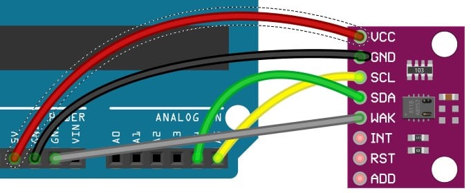
Connect the Sensor’s VCC pin to the 5V pin of the Arduino UNO.
Arduino Code Example For The Arduino and CCS811 VOC Sensor Project
In this section, we will walk through the example Arduino code to verify the VOC sensor module.
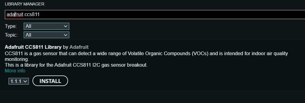
You have to install the Adafruit CCS811 library to use the example code.
- Go to Tools → Manage Libraries
- Search for the Adafruit CCS811 in the search bar and hit Enter
- Please click the INSTALL button once you locate the Adafruit CCS811 library
Project 1: Basic CCS811 sensor test code
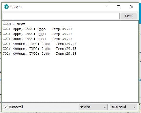
The Arduino code below reads the sensor data over I2C. The data will be printed on the serial terminal.
You can open the terminal to watch the messages.
#include "Adafruit_CCS811.h"

Adafruit_CCS811 ccs;

void setup() {
  Serial.begin(9600);

  Serial.println("CCS811 test");

  if(!ccs.begin()){
    Serial.println("Failed to start sensor! Please check your wiring.");
    while(1);
  }

  // Wait for the sensor to be ready
  while(!ccs.available());
}

void loop() {
  if(ccs.available()){
    if(!ccs.readData()){
      Serial.print("CO2: ");
      Serial.print(ccs.geteCO2());
      Serial.print("ppm, TVOC: ");
      Serial.println(ccs.getTVOC());
    }
    else{
      Serial.println("ERROR!");
      while(1);
    }
  }
  delay(500);
}
The data on the serial terminal displays the messages.
Project 2: Display VOC data on an OLED display
The Arduino code below reads the sensor data over I2C. The data will be displayed on the OLED display.
The OLED display is connected to the Arduino UNO over the I2C line.
/* This demo shows how to display the CCS811 readings on an Adafruit I2C OLED.
 * (We used a Feather + OLED FeatherWing)
 */

#include "SPI.h"
#include "Wire.h"
#include "Adafruit_GFX.h"

#include <"dafruit_SSD1306.h"
#include "Adafruit_CCS811.h"

Adafruit_CCS811 ccs;
Adafruit_SSD1306 display = Adafruit_SSD1306();

void setup() {
  Serial.begin(115200);

  if(!ccs.begin()){
    Serial.println("Failed to start sensor! Please check your wiring.");
    while(1);
  }

  // by default, we'll generate the high voltage from the 3.3v line internally! (neat!)
  display.begin(SSD1306_SWITCHCAPVCC, 0x3C);  // initialize with the I2C addr 0x3C (for the 128x32)

  // Show image buffer on the display hardware.
  // Since the buffer is intialized with an Adafruit splash screen
  // internally, this will display the splash screen.
  display.display();
  delay(500);

  // Clear the buffer.
  display.clearDisplay();
  display.display();

  //calibrate temperature sensor
  while(!ccs.available());
  float temp = ccs.calculateTemperature();
  ccs.setTempOffset(temp - 25.0);

  Serial.println("IO test");

  // text display tests
  display.setTextSize(1);
  display.setTextColor(WHITE);
}


void loop() {
  display.setCursor(0,0);
  if(ccs.available()){
    display.clearDisplay();
    float temp = ccs.calculateTemperature();
    if(!ccs.readData()){
      display.print("eCO2: ");
      Serial.print("eCO2: ");
      float eCO2 = ccs.geteCO2();
      display.print(eCO2);
      Serial.print(eCO2);

      display.print(" ppm\nTVOC: ");
      Serial.print(" ppm, TVOC: ");
      float TVOC = ccs.getTVOC();
      display.print(TVOC);
      Serial.print(TVOC);

      Serial.print(" ppb   Temp:");
      display.print(" ppb\nTemp: ");
      Serial.println(temp);
      display.println(temp);
      display.display();
    }
    else{
      Serial.println("ERROR!");
      while(1);
    }
  }
  delay(500);
}
FAQs About The CCS811 VOC Sensor And Arduino Projects
I have included a list of the most frequently asked questions about projects built using Arduino and the VOC sensor.
If you have more questions, please post them in the comments section.
I will be glad to answer them.
1. What does VOC stand for?
VOC stands for Volatile Organic Compound. The VOCs are a group of chemicals that are commonly found in the materials used to build and maintain the house and household equipment.
The VOCs are later released into the air slowly.
2. What does a VOC sensor measure?
The VOC sensor directly measures the reducing gases which are dangerous to human health.
Some sensors provide the data in PPM and some in the percentage value.
The gases that burn and spread into the air are alcohols, aldehydes, ketones, organic acids, amines, organic chloramines, etc.
3. Which parameters can be measured with a CCS811 sensor?
You can measure the equivalent CO2 (eCO2) with a measurement range of 400 to 8192 PPM (parts per million).
The VOC range is 0 ppb to 1187 ppb. Any values outside the range are clipped.
4. What are the common sources of VOCs?
Common VOCs sources are paints, adhesives, carpets, vinyl flooring, gasoline, cosmetics, photocopiers, dry cleaning, smoking, air fresheners, burning wood, etc.
Conclusion
In this article, we covered the operation and features of the VOC sensor based on the CCS811 sensor.
We covered the connection details and provided some example code to test the connection between Arduino and the CCS811 sensor.
The VOC sensor is a vital part of any air quality monitoring system. It is versatile and easy to use.
You can further enhance the VOC sensor using additional temperature and PM sensors to build a complete air quality monitoring system.
If you have any feedback to improve the article, please share it in the comments section.
Your valuable input helps me to improve the article quality and bring more helpful content in the future.
Kindly remember to share the article with your fellow Arduino enthusiasts.

I am Puneeth. I love tinkering with open-source projects, Arduino, ESP32, Pi and more. I have worked with many different Arduino boards and currently I am exploring, Arduino powered LoRa, Power line communication and IoT.