A soil moisture sensor is the first component you need when considering automation for watering plants.
These sensors help you to make sure that the plants get watered when they need it.
In the world of the Internet of Things, these sensors are the “Things” that make the IoT project complete.
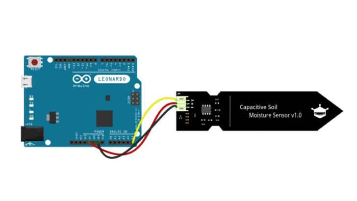
In this article you will learn how to use an Arduino’s capacitive soil moisture sensor.
I will share the required parts, the connection details, the library to use the capacitance soil moisture sensor, and a few examples of Arduino projects.
By the end of the tutorial, you will be confident using the capacitive soil moisture sensor with an Arduino.
I will give a step-by-step guide to connect and read the soil moisture level from the sensor.
I will also provide examples of projects you can use immediately and bring up your own Arduino project with a capacitive soil moisture sensor.
Let’s get started!
Components Needed To Build Arduino And Capacitive Soil Sensor Project
Hardware Components
- Dupont wire x 3
- Arduino USB cable (for powering Arduino and programming) x 1
- Breadboard x 1
Software
Makerguides.com is a participant in the Amazon Services LLC Associates Program, an affiliate advertising program designed to provide a means for sites to earn advertising fees by advertising and linking to products on Amazon.com.
What Is A Capacitive Soil Moisture Sensor?
Traditional soil moisture sensor uses resistance variations to detect the amount of moisture present in the soil.
These sensors were very much prone to degradation due to electrode corrosion.
It means they need a lot of maintenance and lose accuracy soon.
The capacitive soil moisture sensor can detect the moisture without coming in direct contact with the water in the soil.
In this case, you will read the analog value, which is proportional to the moisture in the ground.
The moisture in the soil changes the dielectric value, thereby changing the read capacitance.
The sensor converts its capacitance into an analog value, which you can read using Arduino’s analog inputs.
Most of the sensors come in a wide range of supply voltage. You can connect the sensors to 3.3 V and 5 V Arduino boards.
The benefits of using the capacitive soil moisture sensor are
- No need to calibrate the sensor frequently
- No loss of accuracy over time
- No corrosion of the sensor
There are several suppliers from where you can buy the capacitive soil moisture sensors.
In this demo, I use the most common one I find easy to buy.
Here is an interesting article for your later reading where several capacitive soil moisture sensors are tested.
Step-By-Step Instructions To Connect A Capacitive Soil Moisutre Sensor To Arduino
I will show you how to make the capacitive soil moisture sensor work with the Arduino in the following section.
-> Read our guide about What You Can Build with Adruino.
How To Connect Capacitive Soil Sensor To Arduino
Here are the connection details necessary to complete the Arduino and the capacitive soil moisture sensor
Step 1: Start with the Capacitive soil moisture sensor
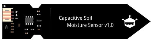
You can see that there are three pins to the left side of the sensor available for connection.
The table below gives you the pin labels and their description.
Do you also see the vertical white marker on the sensor? Please do not immerse the sensor in the soil beyond that line for reliable data collection.
| Pin label / marking | Pin function |
| A or AOUT or OUT | Analog Output (the equivalent of the soil moisture) |
| + or V+ VCC or 5V | Positive Supply voltage (most of the sensors are 3.3 V to 5 V compatible) |
| GND or – or V- | Ground connection |
Step 2: Make the Ground connection
Connect one of the GND pin the Arduino to the “-” labeled pin on the capacitive sensor.
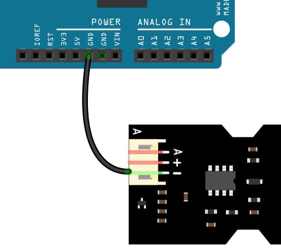
It is always a wise idea to start with the ground connection.
You will be sure that the voltage is referenced to the same point when making connections while the Arduino is powered.
Step 3: Connect the Analog Output signal to the Arduino
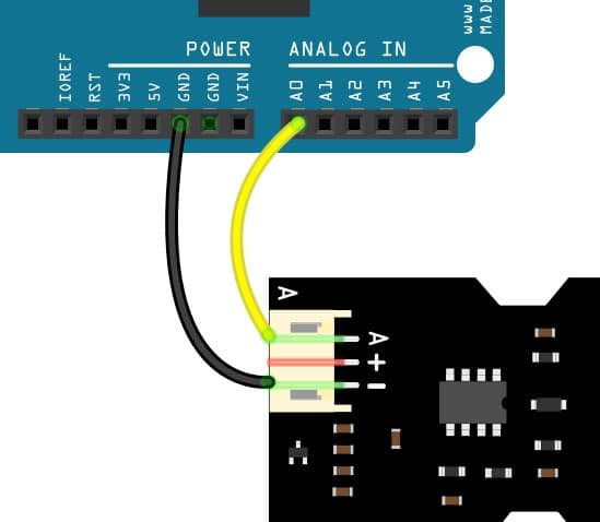
Connect the Sensor pin labeled “A” to the Arduino analog input pin. There are several analog input pins on the Arduino.
Depending on the Arduino board you have, you can choose the analog pin which is most suitable.
I have chosen analog Pin A0. You can follow the library-suggested analog pin.
You can also update the Arduino Sketch to select the desired analog input pin for the sensor connection.
Step 4: Connect the Power Pins to supply the capacitive soil moisture sensor
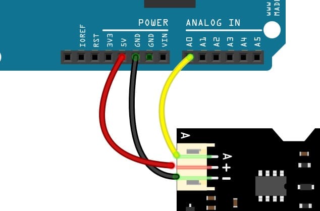
Connect the Sensor pin labeled “+” to the Arduino 5 V pin. The right selection of voltage ensures that the analog signal is interpreted in the right way.
If you use Arduino UNO, connect the “+” pin to the 5V pin on the Arduino UNO.
If it is an Arduino Mega, connect it to the 3.3 V pin.
Congrats! You have now completed the hardware connections.
In the next section, you will set up the required libraries to make the project work.
Simple Arduino Code For Capacitive Soil Moisture Sensor
Here is the code for reading the soil moisture sensor value using an Arduino board.
I have explained the logic in the later section. The logic is simple to follow and easy to customize.
const int OpenAirReading = 700;   //calibration data 1
const int WaterReading = 280;     //calibration data 2
int MoistureLevel = 0;
int SoilMoisturePercentage = 0;

void setup() {
  Serial.begin(9600); // open serial port, set the baud rate to 9600 bps
}

void loop() {
  MoistureLevel = analogRead(A0);  //update based on the analog Pin selected
  Serial.println(soilMoistureValue);
  SoilMoisturePercentage = map(MoistureLevel, OpenAirReading, WaterReading, 0, 100);

  if (SoilMoisturePercentage >= 100)
  {
    Serial.println("\n Maximum - 100 %");
  }
  else if (SoilMoisturePercentage <= 0)
  {
    Serial.println("\n Minimum - 0 %");
  }
  else if (SoilMoisturePercentage > 0 && SoilMoisturePercentage < 100)
  {
    Serial.print(SoilMoisturePercentage);
    Serial.println("%");
  }

  delay(1000);
}
Let us go through the key sections of the code to understand the logic.
const int OpenAirReading = 700;   //calibration data 1
const int WaterReading = 280;     //calibration data 2
You may be wondering about the magic numbers I have used in the code. The variables have values set to 700 and 280 in my code.
700 is the analog value read from the sensor when the sensor is in the open air (implies zero moisture).
280 is the analog value when you insert the capacitive soil moisture sensor into the water completely. (implies 100 moisture).
In your case, depending on the sensors, these values may change. These two values are later used in the code to map the sensor’s moisture between 0% and 100%.
In the below lines, you declare two variables to read the analog value and to calculate the soil moisture level in percentage.
int MoistureLevel = 0;
int SoilMoisturePercentage = 0;
We are enabling serial communication to see the data on the serial monitor window on Arduino.
You may not need this in the actual application.
Printing the values helps you to debug quicker, fix bugs faster, and complete the project sooner during development.
Serial.begin(9600);
The below line reads the analog value. The below line of code will return a value between 0 and 1023.
This code will return the numeric value equivalent to the moisture level sensed by the capacitive sensor electrodes.
MoistureLevel = analogRead(A0);
In my connection diagram, you can see that I have used analog input A0. If you are using a different analog input than A0, you must update the above line of code.
SoilMoisturePercentage = map(MoistureLevel, OpenAirReading, WaterReading, 0, 100);
The above line of code remaps the analog value read from the sensor to a value between the minimum and maximum expected moisture level.
You can find more information on the map() function along with some examples here.
Feel free to change the logic, and add more functionalities to make this code useful in your next project.
For example, you may turn on an alarm if the moisture level is too low.
FAQ’s About The Arduino Capacitive soil moisture sensor
In this section, you will find answers to the most frequent questions on the Capacitive soil moisture sensor projects.
Please drop the questions in the comment box if this section doesn’t answer your question.
1) How do you use a capacitive soil moisture sensor with an Arduino?
A capacitive soil moisture sensor is a very easy-to-use sensor. It provides the moisture level through the analog output.
You can monitor the analog values using Arduino and calculate the moisture level.
For step-by-step procedure on how to read the sensors and the connection diagram, refer to the sections above.
2) What is a capacitive soil moisture sensor?
A capacitive soil moisture sensor provides you with the moisture level present in the soil in the form of analog voltage.
Any Arduino board can read the analog values and convert them to equivalent soil moisture content.
Capacitive soil moisture sensors usually come with three or four-pin connections. The connections are easy to make.
You can refer to the sections above to quickly get an overview of the sensor connections.
3) How do you calibrate the capacitive soil moisture sensor using Arduino?
Here is an easy way to calibrate the capacitive soil moisture sensor:
- Prepare the hardware by connecting the capacitive soil moisture sensor to the Arduino
- Prepare an empty and dry beaker
- Fill the dry soil inside
- Immerse the capacitive sensor inside the soil
- Note down the readings. This reading represents the minimum capacitance value
- Now, add water into the beaker carefully until the soil is almost saturated
- Wait for a minute
- Reread the capacitance value. This reading denotes the maximum value
- Use these values to map the moisture level read from the actual application between 0 % to 100 %
Use the minimum and maximum values read in the steps above in the Arduino example code shared in the earlier section.
Depending on the type of plants, the 100 % soil moisture threshold might differ. In this case, you can calibrate based on the application.
The idea is that you should not let the moisture go down or higher than the conditions suitable for the plant.
4) Which is better resistive or capacitive soil moisture sensor?
Both Resistive and capacitive soil moisture sensors have their own merits. Resistive-based soil moisture sensors are cheaper compared to capacitive soil moisture sensors.
The capacitive soil moisture sensor is highly immune to environmental elements as the electrodes don’t come in direct contact with the soil moisture.
The resistive soil moisture sensors suffer from a process called electrolysis which happens due to the salts in the water reacting with the electrode when there is a current flow between the electrodes.
Over a while, the measurements will have huge offsets and errors due to the corrosion of the electrodes.
If you plan to monitor the soil moisture sensors using the resistive type, you can monitor the values periodically instead of keeping the sensor powered all the time.
One idea is to connect the 5 V line of the sensor to an Arduino GPIO.
Whenever measurements are needed, you can drive the GPIO pin high. Once you take the readings, you can drive the GPIO low.
Low frequent readings reduce the risk of electrolysis significantly.
If you have to use the sensor measurements frequently, capacitive sensors are a better design choice.
5) How do capacitive soil sensors work?
The capacitive soil moisture sensor measures the capacitance. The typical circuit components needed are an RC circuit and a timer.
Usually, you can find a 555 timer IC and an opamp in the signal conditioning circuit. There are two electrodes separated by a small distance.
When the soil moisture changes, the dielectric will change.
The capacitance is directly proportional to the dielectric. Hence, a change in the soil moisture changes the capacitance.
The dielectric of water is about 80. Dielectric of air is about 1.
Therefore, when there is an increase in moisture, you will see an increase in capacitance.
Conclusion
In this article, I have shared all the details necessary to build your next soil moisture sensor project.
I hope you have enjoyed reading the article. If you have any suggestions or questions, kindly drop them in the comments section.
I have used a soil moisture sensor and a simple servo motor to enable automatic watering of the plants.
I hope you have found all the information you need for your moisture sensor project.
Did you find this article beneficial? Do you have any suggestions to make this article more reader-friendly?
Please reply in the comments. Please share the article with your friends too.
I will be excited to hear about your capacitive soil moisture sensor projects.
Please leave the link to the project you built.
I will be happy to follow the link and watch your projects!

I am Puneeth. I love tinkering with open-source projects, Arduino, ESP32, Pi and more. I have worked with many different Arduino boards and currently I am exploring, Arduino powered LoRa, Power line communication and IoT.
Jeff Verive
Monday 27th of February 2023
There's an error in your code. You declare a variable called "MoistureLevel", but use a different (undeclared) variable called "soilMoistureValue" when displaying the raw analog value via the second line in the main loop:
Serial.println(soilMoistureValue);
Because "soilMoistureValue" is not declared elsewhere, the compiler throws an error. If you replace "soilMoistureValue" with "MoistureLevel" the sketch runs as intended.