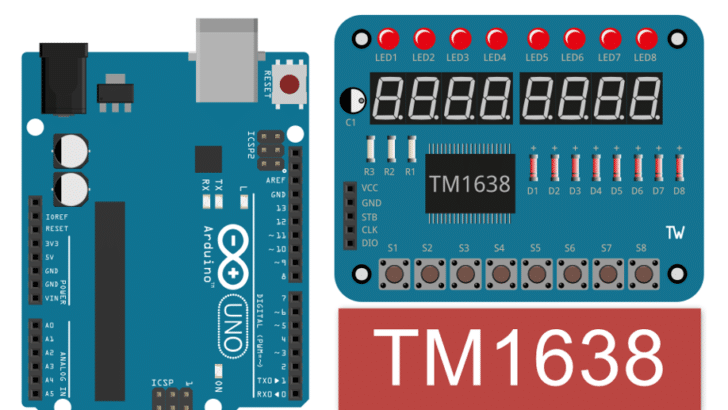
In this article, I will show you how the TM1638 7-segment LED driver IC works and how to connect it to an Arduino UNO.
I have used the LED driver IC TM1638 in earlier projects, since it offloads a tremendous amount of work from the host MCU. Adding the LED driver IC to your project is easy and simple.
I will start by taking you through the LED driver specifications, sharing tips and tricks, and showing you how to display digits and scan the buttons.
We then will go into more detail and look at the connection guide and Arduino code for the TM1638 LED driver IC LCD parallel data interface. We also answer frequently asked questions.
Grab your Arduino board, and let’s get started!
Components Needed To Build Arduino And TM1638 Project
Hardware Components
- Arduino UNO x 1
- Arduino Compatible TM1638 display module x 1
- Dupont wire x 1 set
- USB Cable for Arduino Programming x 1
Software
Fundamentals Of The TM1638 LED Driver Module
Let us understand the main features of the TM1638 LED driver IC first:
- Control 8 digits ( 7 segments)
- Drive 8 LEDs
- Scan eight tactile switches
- You can control the brightness
- Serial interface – CLK, DIO, STB
A typical connection between the Arduino and the TM1638 driver IC is shown in the below image.

In the next section, we will learn about the interfaces between various peripherals and TM1638.
Pin details of the TM1638 LED driver IC
| Pin name | Pin type | Pin Description |
| DIO | Data input/output | Serial data between Arduino and the TM1638 driver IC |
| STB | Chip select | Initialize serial interface during the falling/rising edge, then receive instruction. The first byte is instruction when STB is low. CLK will be ignored when STB is high. |
| CLK | Clock input | Output input at the serial data |
| K1 ~ K3 | Key-scan data input | Data inputted into the Pin will be latched after display cycle closes. |
| SEG1/KS1 ~ SEG8/KS8 | Output (segment) | Segment output. Open drain output. |
| SEG9 ~ SEG10 | Output (segment) | Segment output. Open drain output. |
| GRID1 ~ GRID8 | Output (grid) | Grid output. Open drain output. |
| VDD | Logic Power | 5 V ± 10% |
| GND | Logic ground | Ground connections |
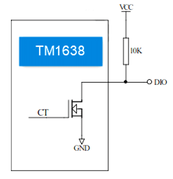
A special note about the DIO pin: The Digital-Input-Output (DIO) pin in the TM1638 module is an N-type open drain. You should provide an external pull-up to pull the DIO line to logic high. The recommended value is 10 kOhms. See circuit below:
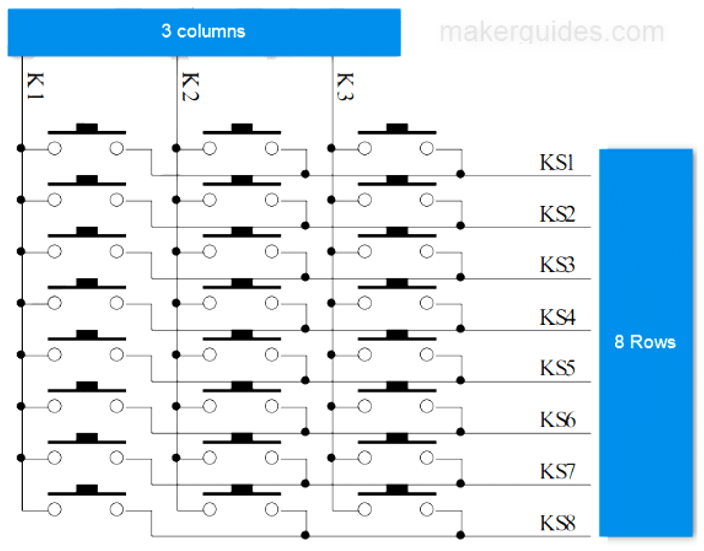
Key Scanning and Key-scan data register
The key scan frame rate is 8 x 3 bit. It is similar to rows and columns. You can consider this as eight rows and three columns matrix. It means you can use up to 24 push buttons.
In the below image, you can see how to utilize the chip K and KS pins of the TM1638 driver IC to scan 24 buttons
Instruction set
You can use B7 and B6 bits of the DIO bit to decide the type of instruction. The TM1638 IC uses the below decoding mechanism to identify the type of instruction sent by the Arduino.
| B7 | B6 | Instruction |
| 0 | 1 | Data Instruction set |
| 1 | 0 | Display control instruction set |
| 1 | 1 | Address Instruction set |
Data instruction set.
Typically, you will mostly use the data instruction set. It is responsible for the reading and writing of data. Note: B1 and B0 must not be set to 01 and 11 for this instruction set.
| B7 | B6 | B5 | B4 | B3 | B2 | B1 | B0 | Function | Instruction |
| 0 | 1 | 0 | 0 | 0 | 0 | 0 | 0 | Data write mode set | Write data to register |
| 0 | 1 | 0 | 0 | 0 | 0 | 1 | 0 | Read key-scan data | |
| 0 | 1 | 0 | 0 | 0 | 0 | 0 | 0 | Address add mode set | Auto address add |
| 0 | 1 | 0 | 0 | 0 | 1 | 0 | 0 | Fixed address | |
| 0 | 1 | 0 | 0 | 0 | 0 | 0 | 0 | Test mode | Normal mode |
| 0 | 1 | 0 | 0 | 1 | 0 | 0 | 0 | Test mode |
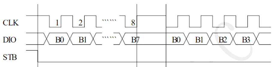
In the images below, you can see the timing and clocking pattern of both writing and reading from the TM1638 IC.
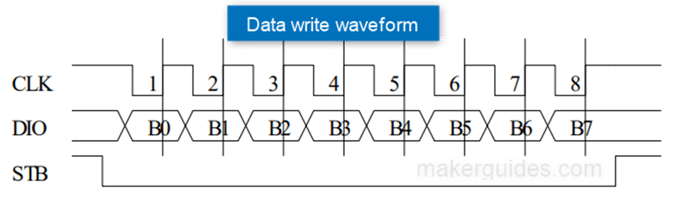
Note that when you are reading the data from the chip, you have to insert at least a 1 us delay between the instruction and the data reception. This is mandatory.
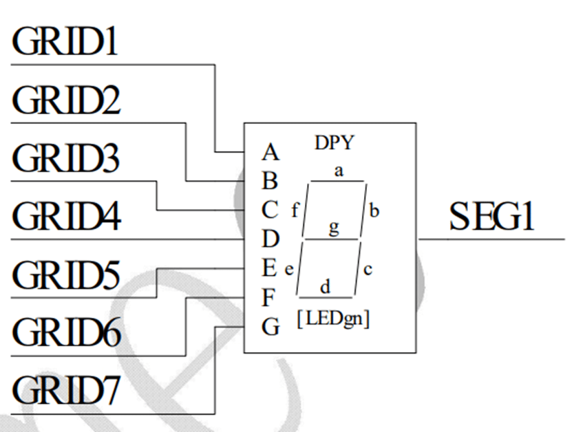
To find out how to connect the TM1638 display pins to the LED 7-segment display, refer to the image below. The below example is for the common cathode type of display, In this case all cathode pins of the LEDs are connected together.
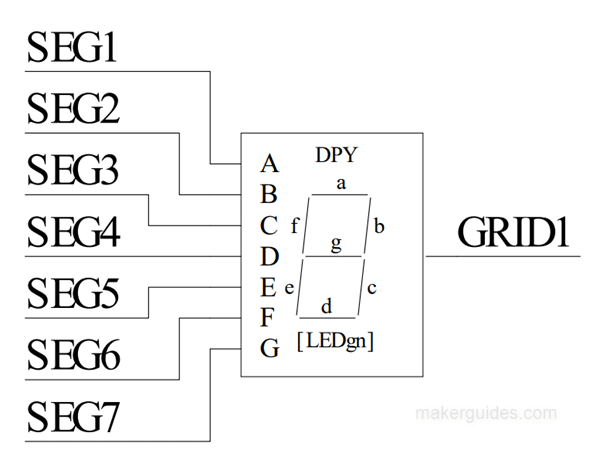
An alternative is the common anode type of display, where all anode pins of the LEDs are connected together.
It is important to know the electrical specifications of the chip you are working with. It will help you to debug, and also ensure that you don’t destroy the chip. The more you know about the specifics of the IC, the easier it will be to make connections and build reliable circuits.
Below are the electrical specifications of the TM1638 LED driver IC:
| Parameter | Range |
| Logic power voltage | Typical 5 V |
| High-level input voltage | 0.7 x VDD minimum |
| Low-level input voltage | 0.3 X VDD maximum |
| High-Level output current | 40 mA maximum |
| Low-level output current | 140 mA maximum |
| Active current consumption | 5 mA maximum |
| Max Clock frequency | 1 MHz |
| Input capacity | 15 pF |
Enough of the basics ; ) In the next sections, let’s build the project!
How To Connect The TM1638 To the Arduino UNO
I will now show you how to build a project using Arduino UNO and the TM1638 display module. Let’s get started with the hardware connections.
Here is the connection summary needed to connect the Arduino UNO to the TM1638 module. I hope it gives an overall connection overview. Follow along for the connection guide.
| Pin on TM1638 Module | Arduino UNO pin | Remarks |
| VCC | 5 V | Power supply |
| GND | GND | Ground connections |
| STB | Strobe line, Pin 8 | Any IO pin |
| CLK | Data line, pin 10 | Any IO pin |
| DIO | Clock line, pin 9 | Any IO pin |
Step 1: Complete the TM1638 and the Arduino UNO
Here is the connection diagram between Arduino UNO and the TM1638 chip.
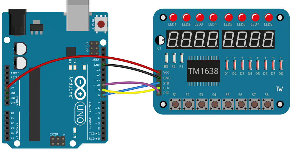
Serial data uses only two wires. This helps you to save pins on the board and also reduces the number of wires.
The serial protocol used by TM1638 is not a standard one. But no need to worry. There are excellent libraries that you can use! You can find one such library here.
Always remember to start with the ground connections. Wait to supply power to the project until all the connections are made.
Step 2: Program the Arduino UNO code below
Follow the next step to understand the code implementation. You can use the code below to test the TM1638 module. We are not using any libraries here.
const int strobe = 8; // STB to D8
const int clock = 10; // CLK to D10
const int data = 9;   // DIO to D9

void sendCommand(uint8_t value)
{
  digitalWrite(strobe, LOW);
  shiftOut(data, clock, LSBFIRST, value);
  digitalWrite(strobe, HIGH);
}

void reset()
{
  sendCommand(0x40); // Set auto increment mode
  digitalWrite(strobe, LOW);
  shiftOut(data, clock, LSBFIRST, 0xc0);   // Set starting address to 0
  for (uint8_t i = 0; i < 16; i++)
  {
    shiftOut(data, clock, LSBFIRST, 0x00);
  }
  digitalWrite(strobe, HIGH);
}

void setup()
{
  pinMode(strobe, OUTPUT);
  pinMode(clock, OUTPUT);
  pinMode(data, OUTPUT);
  sendCommand(0x8f);  // Set maximum display brightness
  reset();
}

#define COUNTING_MODE 0
#define SCROLL_MODE 1
#define BUTTON_MODE 2

void loop()
{
  static uint8_t mode = COUNTING_MODE;
  switch (mode)
  {
    case COUNTING_MODE:
      mode += counting();
      delay(500);
      break;
    case SCROLL_MODE:
      mode += scroll();
      break;
    case BUTTON_MODE:
      buttons();
      break;
  }
  delay(200);
}

bool counting()
{
  /*0*/ /*1*/ /*2*/ /*3*/ /*4*/ /*5*/ /*6*/ /*7*/ /*8*/ /*9*/
  uint8_t digits[] = { 0x3f, 0x06, 0x5b, 0x4f, 0x66, 0x6d, 0x7d, 0x07, 0x7f, 0x6f };
  static uint8_t digit = 0;
  sendCommand(0x40);
  digitalWrite(strobe, LOW);
  shiftOut(data, clock, LSBFIRST, 0xc0);
  for (uint8_t position = 0; position < 8; position++)
  {
    shiftOut(data, clock, LSBFIRST, digits[digit]);
    shiftOut(data, clock, LSBFIRST, 0x00);
  }
  digitalWrite(strobe, HIGH);
  digit = ++digit % 10;
  return digit == 0;
}

bool scroll()
{
  uint8_t scrollText[] =
  {
    /* */ /* */ /* */ /* */ /* */ /* */ /* */ /* */
    0x00, 0x00, 0x00, 0x00, 0x00, 0x00, 0x00, 0x00,
    /*H*/ /*E*/ /*L*/ /*L*/ /*O*/ /*.*/ /*.*/ /*.*/
    0x76, 0x79, 0x38, 0x38, 0x3f, 0x80, 0x80, 0x80,
    /* */ /* */ /* */ /* */ /* */ /* */ /* */ /* */
    0x00, 0x00, 0x00, 0x00, 0x00, 0x00, 0x00, 0x00,
    /*H*/ /*E*/ /*L*/ /*L*/ /*O*/ /*.*/ /*.*/ /*.*/
    0x76, 0x79, 0x38, 0x38, 0x3f, 0x80, 0x80, 0x80,
  };
  static uint8_t index = 0;
  uint8_t scrollLength = sizeof(scrollText);
  sendCommand(0x40);
  digitalWrite(strobe, LOW);
  shiftOut(data, clock, LSBFIRST, 0xc0);

  for (int i = 0; i < 8; i++)
  {
    uint8_t c = scrollText[(index + i) % scrollLength];
    shiftOut(data, clock, LSBFIRST, c);
    shiftOut(data, clock, LSBFIRST, c != 0 ? 1 : 0);
  }

  digitalWrite(strobe, HIGH);
  index = ++index % (scrollLength << 1);
  return index == 0;
}

void buttons()
{
  uint8_t promptText[] =
  {
    /*P*/ /*r*/ /*E*/ /*S*/ /*S*/ /* */ /* */ /* */
    0x73, 0x50, 0x79, 0x6d, 0x6d, 0x00, 0x00, 0x00,
    /* */ /* */ /* */ /* */ /* */ /* */ /* */ /* */
    0x00, 0x00, 0x00, 0x00, 0x00, 0x00, 0x00, 0x00,
    /*b*/ /*u*/ /*t*/ /*t*/ /*o*/ /*n*/ /*S*/ /* */
    0x7c, 0x1c, 0x78, 0x78, 0x5c, 0x54, 0x6d, 0x00,
    /* */ /* */ /* */ /* */ /* */ /* */ /* */ /* */
    0x00, 0x00, 0x00, 0x00, 0x00, 0x00, 0x00, 0x00,
  };
  static uint8_t block = 0;
  uint8_t textStartPos = (block / 4) << 3;

  for (uint8_t position = 0; position < 8; position++)
  {
    sendCommand(0x44);
    digitalWrite(strobe, LOW);
    shiftOut(data, clock, LSBFIRST, 0xC0 + (position << 1));
    shiftOut(data, clock, LSBFIRST, promptText[textStartPos + position]);
    digitalWrite(strobe, HIGH);
  }

  block = (block + 1) % 16;
  uint8_t buttons = readButtons();

  for (uint8_t position = 0; position < 8; position++)
  {
    uint8_t mask = 0x1 << position;
    setLed(buttons & mask ? 1 : 0, position);
  }
}

uint8_t readButtons(void)
{
  uint8_t buttons = 0;
  digitalWrite(strobe, LOW);
  shiftOut(data, clock, LSBFIRST, 0x42);
  pinMode(data, INPUT);

  for (uint8_t i = 0; i < 4; i++)
  {
    uint8_t v = shiftIn(data, clock, LSBFIRST) << i;
    buttons |= v;
  }

  pinMode(data, OUTPUT);
  digitalWrite(strobe, HIGH);
  return buttons;
}

void setLed(uint8_t value, uint8_t position)
{
  pinMode(data, OUTPUT);
  sendCommand(0x44);
  digitalWrite(strobe, LOW);
  shiftOut(data, clock, LSBFIRST, 0xC1 + (position << 1));
  shiftOut(data, clock, LSBFIRST, value);
  digitalWrite(strobe, HIGH);
}
Step 3: Code Walkthrough
Let’s walk through the code.
const int strobe = 8; // STB to D8
const int clock = 10; // CLK to D10
const int data = 9;   // DIO to D9
strobe, clock, and data are constants representing the PINs connected to the display module’s STB, CLK, and DIO pins, respectively.
void sendCommand(uint8_t value)
This function sends a command to the display module. It sets the STB pin low, shifts out the command byte using the shiftOut() function, and then sets the STB pin high
void reset()
This function resets the display module to its initial state.
It calls sendCommand() to send commands to set the auto-increment mode and reset the starting address. It then uses a loop to shift out 16 bytes of value 0x00 to clear the display.
The setup() function does the following tasks once:
It sets the pin modes for the STB, CLK, and DIO pins. It calls sendCommand() to activate the display with maximum brightness. Finally, it calls reset() to initialize the display.
The loop() function is called repeatedly after the `setup()` function. The loop() function is the main program loop that runs continuously. It uses a static variable mode to keep track of the current mode.
void loop()
It uses a switch statement to execute different actions based on the current mode:
COUNTING_MODE calls the counting() function and increments the mode when the counter reaches a specific condition.
SCROLL_MODE calls the scroll() function and increments the mode when the scrolling reaches a particular condition.
BUTTON_MODE calls the buttons() function to handle button inputs.
It includes delay periods between actions. I hope it helps.
FAQs About The TM1638 LED Driver IC
Below you will find a list of the most frequently asked questions about projects built using the Arduino UNO and the TMP1638 LED driver IC.
If you have other questions, drop them in the comments section.
What is a TM1638 display module?
The TM1638 display module is a popular option for hobbyists to interface with LED displays, buttons, and other peripherals. It integrates a display controller and a keypad scanner. This makes it easy to control and interact with various inputs and outputs.
How does the TM1638 display module communicate with a microcontroller?
The TM1638 module communicates with a microcontroller using a simple serial communication protocol.
To send and receive data requires three control lines (data, clock, and strobe). Please refer to the basics section in the article to understand in detail about the communication protocol.
What are the main features of the TM1638 display module?
The TM1638 module typically offers eight 7-segment LED displays, a set of LED indicators, and several tactile buttons. It also provides brightness control for the display and supports multiplexing to reduce the required I/O pins.
Can I control multiple TM1638 modules with a single microcontroller?
It is possible to control multiple TM1638 modules with a single microcontroller. Each module can be assigned a unique address through hardware addressing, allowing them to be individually controlled in a multi-module setup.
What microcontrollers are compatible with the TM1638 display module?
The TM1638 module can be interfaced with various microcontrollers, including popular ones like Arduino, Raspberry Pi, and ESP8266. As long as the microcontroller supports digital I/O and serial communication, it can be used with the module.
One important aspect is to ensure voltage compatibility between the microcontroller and the TM1638 module.
Are there libraries available for programming the TM1638 display module?
Yes, various libraries are available for different platforms and programming languages to simplify the integration of the TM1638 module.
These libraries provide functions and abstractions to control the display, read button inputs, and handle other module features. Please refer to the Arduino Code section to find useful libraries.
Can I use the TM1638 display module for projects other than the primary display and button input?
Absolutely! The TM1638 module is versatile and can be used beyond primary display and button functionality for many projects.
Conclusion
This article has covered all the essential information about using the TM1638 with the Arduino UNO.
Was the article easy to follow? If you have suggestions to improve the article, you are always welcome to share feedback.
I’d love to hear from you! Let us know if there’s anything else you’d like me to cover in future articles.

I am Puneeth. I love tinkering with open-source projects, Arduino, ESP32, Pi and more. I have worked with many different Arduino boards and currently I am exploring, Arduino powered LoRa, Power line communication and IoT.