In this article, I will show you how to use the RGB color sensor TCS34725 with an ESP32 microcontroller to measure the color temperature of an object and the lux information.
The color sensor TCS34725 is used in industrial process control, food processing industries, sorting facilities, smartphones, tabs, large TV monitors, and appliances for ambient light detection..
The RGB sensor TCS34725 is an exact and powerful sensor. The sensitivity is excellent, so you can keep the sensor inside a glass, protect it, and still make it work for color and ambient light detection applications.
It also has exciting features loaded, making it my number one choice for color-sensing applications.
This article will show you how to use a TCS34725 color sensor with an ESP32. I share a wiring connection guide, example ESP32 code for the color sensor, and also answer some frequently asked questions about the TCS34725.
Let’s get started!
Components Needed To Build ESP32 And RGB Sensor TCS34725 Project
Hardware Components
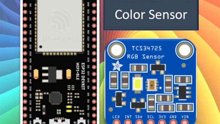
- ESP32 Wroom 2.4 GHz with integrated Antenna x 1
- RGB Color Sensor Module – TCS34725 x 1
- Dupont wire x 1 set
- Micro USB Cable for ESP32 (for powering ESP32 and programming) x 1
Software
Guide
Fundamentals Of The TCS34725 RGB Color Sensor
Let us understand the basic working principle, features, pinouts, and applications of the RGB color sensor. Knowing these details makes you confident in choosing the TCS34725 RGB sensor for suitable applications.
The TCS34725 is a color-to-digital sensor. It can sense:
- Red
- Green
- Blue
- And clear light
At a high level, the diagram below illustrates what the TCS34725 does. The light enters the sensor through an Infra-red (IR) filter. The four independent sensors are only sensitive to a particular light color input.
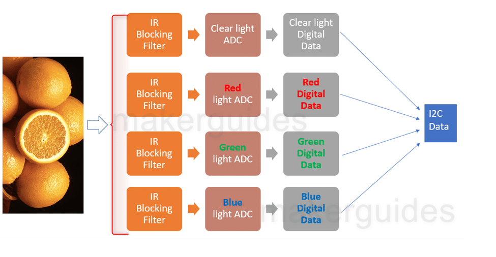
The sensors will give an analog value converted into a digital value by 4 Analog-to-digital converters (ADCs) internal to the color sensor. The data can be read using I2C.
You can now use this information to build color and ambient light sensors and other valuable projects.
Here is the block diagram of the sensor.
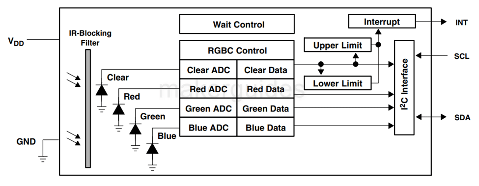
I will explain the critical concepts you need to know!
Characteristics
The photodiodes are used to sense the amount of light falling on them. The photodiode’s current varies according to the light falling on them. Take photodiode characteristics for an example.
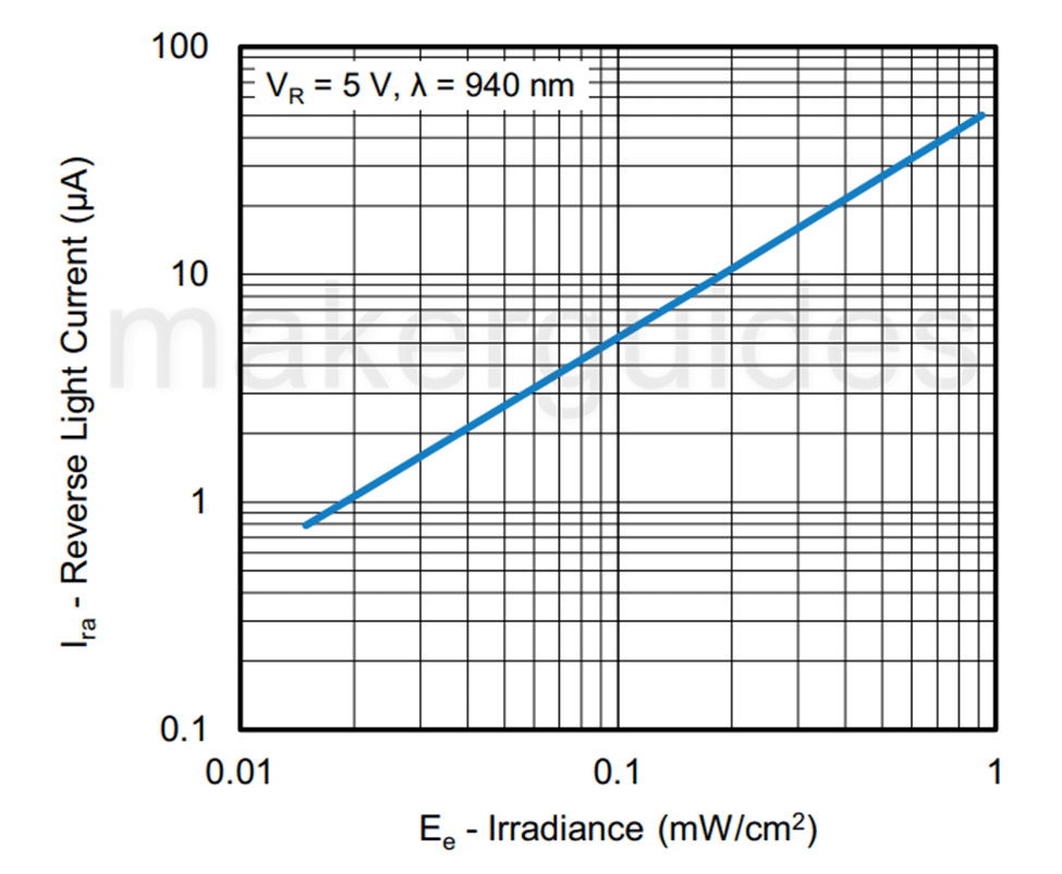
The diagram above shows that as the light intensity increases, the reverse current increases. In the case of the color sensor, the photodiodes have a red filter, green filter, blue filter, and no filter.
So, the photodiode with a red filter only sees the RED color and nothing else. In other words, the diode will only respond to the RED color.
Similarly, the green and blue photodiodes only respond to green and blue colors. The fourth photodiode will respond to all colors (no filter). Sounds easy?
4 ADCs simultaneously convert this photodiode current into digital values, which you can read using the ESP32.
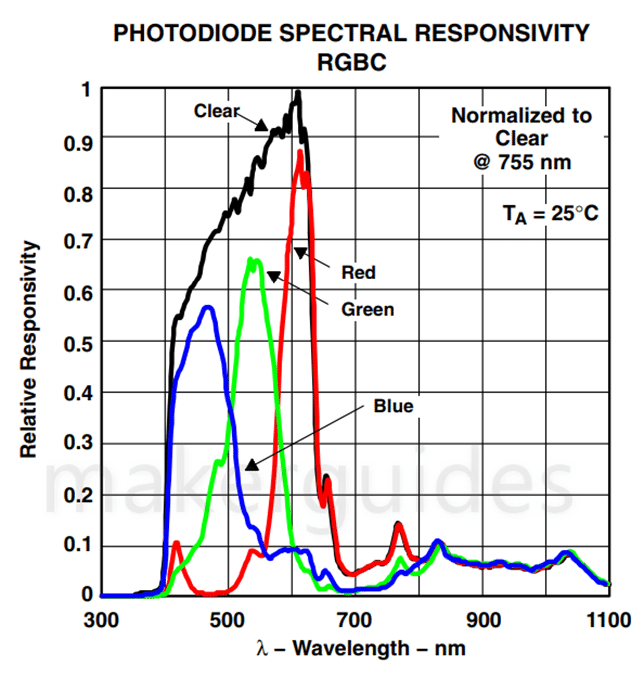
Responsivity
For a test light source, here is how the sensor TCS34725 responds.
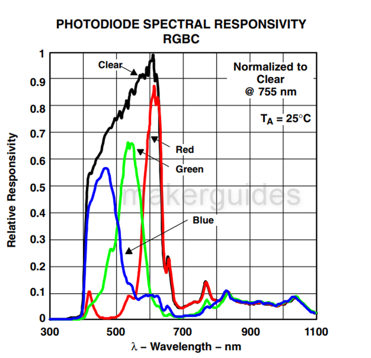
You can see how the four color sensors are sensitive to corresponding colors.
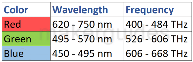
For example, the Blue sensor peaks above 450 nm and up to 500 nm. Similarly, the green and red light sensors are peaking at a particular wavelength.
Refer to the table below for the colors and corresponding wavelength range.
I will now teach about all the internal registers of the color sensor TCS34725. It will help you in setting them in the future for your particular need, such as adding more wait time or increasing the gain (for low light conditions), etc.
Before I present all the registers, I want to show you a table where you can understand how the register settings affect conversion time and current consumptions.
In the table below, you can see how the average current consumption of the device varies as you enable different wait durations using WEN, WTIME, and WLONG bits.
| WEN | WTIME | WLONG | WAIT STATE | AVERAGE IDD CURRENT |
| 0 | n/a | n/a | 0 ms | 291 μA |
| 1 | 0xFF | 0 | 2.40 ms | 280 μA |
| 1 | 0xEE | 0 | 43.2 ms | 152 μA |
| 1 | 0x00 | 0 | 614 ms | 82 μA |
| 1 | 0x00 | 1 | 7.37 s | 67 μA |
You choose the tradeoff between current consumption and speed!
TCS34725 Registers
Below, you will find the registers and their meaning. I will brief you about all the registers in the next section.
| Address | Register Name | Register function | Reset value |
| −− | COMMAND | Specifies register address | 0x00 |
| 0x00 | ENABLE | Enables states and interrupts | 0x00 |
| 0x01 | ATIME | RGBC time | 0xFF |
| 0x03 | WTIME | Wait time | 0xFF |
| 0x04 | AILTL | Clear interrupt low threshold low byte | 0x00 |
| 0x05 | AILTH | Clear interrupt low threshold high byte | 0x00 |
| 0x06 | AIHTL | Clear interrupt high threshold low byte | 0x00 |
| 0x07 | AIHTH | Clear interrupt high threshold high byte | 0x00 |
| 0x0C | PERS | Interrupt persistence filter | 0x00 |
| 0x0D | CONFIG | Configuration | 0x00 |
| 0x0F | CONTROL | Control | 0x00 |
| 0x12 | ID | Device ID | ID |
| 0x13 | STATUS | Device status | 0x00 |
| 0x14 | CDATAL | Clear data low byte | 0x00 |
| 0x15 | CDATAH | Clear data high byte | 0x00 |
| 0x16 | RDATAL | Red data low byte | 0x00 |
| 0x17 | RDATAH | Red data high byte | 0x00 |
| 0x18 | GDATAL | Green data low byte | 0x00 |
| 0x19 | GDATAH | Green data high byte | 0x00 |
| 0x1A | BDATAL | Blue data low byte | 0x00 |
| 0x1B | BDATAH | Blue data high byte | 0x00 |
Command Register
The command register specifies the address of the target register for future write and read operations. You use this command to select a protocol transaction type.
You choose which register you want to read from or write to using this command register.
Enable register
The Enable register is used primarily to power the TCS3472 device on and off, and enable functions and interrupts.
RGBC Timing Register
The RGBC timing register controls the internal integration time of the RGBC clear and IR channel ADCs in 2.4-ms increments
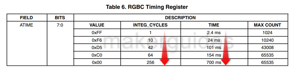
Increasing the integration time improves the sensitivity at the cost of time. If you are okay to spend a few 100 ms, I recommend choosing longer integrating times.
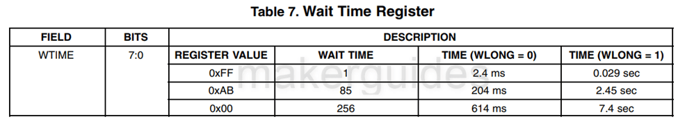
Wait Time Register
You use the wait time register to insert wait times between conversions. It helps you bring down average current consumption.
RGBC Interrupt Threshold Registers
You use these registers to set the ADC signal thresholds. The color sensor IC will assert the INT (interrupt) signal if the color read crosses this threshold. Useful when you want to take action when the color mixing process goes wrong (industrial production, for example).
Persistence Register
The persistence register is in charge of controlling how the device filters interrupts. You can configure it so that you get an interrupt after every integration cycle or when the integration goes beyond the values set by the threshold register for a specific period of time.
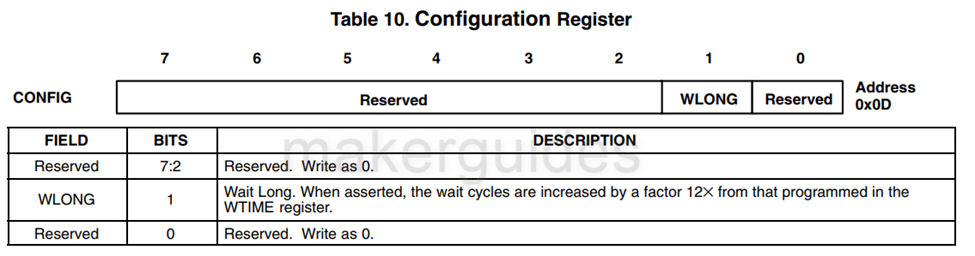
Configuration Register
The register helps you to set the wait long time. Whatever you write 1 to WLONG bit, the delay ( programmed in the WTIME register) will be multiplied by 12x.
Control Register
The Control register gives you eight bits to play with and control a bunch of different things in the analog block. These bits are used to tweak the gain settings and other similar functions.
ID Register
Provides you the ID of the IC. It is a read only register. For TCS34725 the ID will be 0x44. For TCS34723, it will be 0x4D.
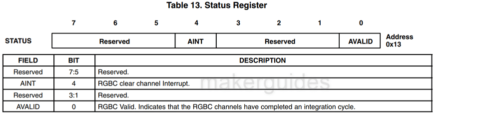
Status Register
You can read the internal status of the IC using this register.
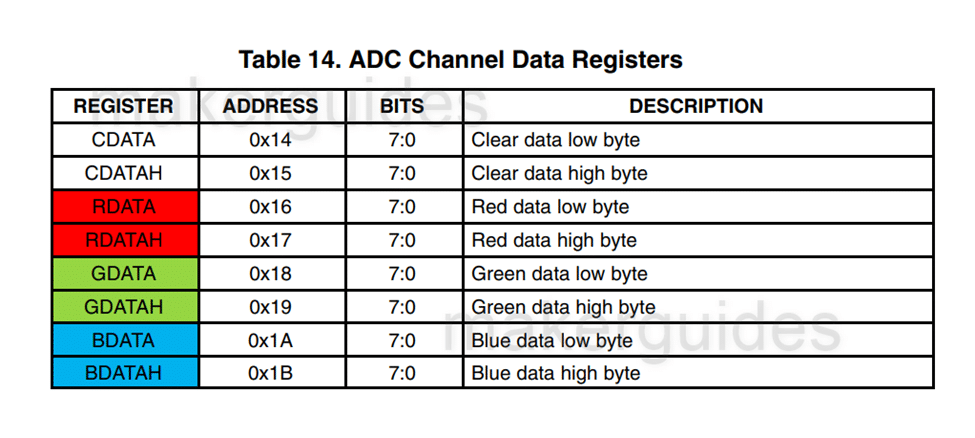
RGBC Channel Data Registers
Last but not least, this is the register you would read all the time! You can get the digital sensor data for R, G, b, and clear light data here.
How to program a particular integration time?
Let’s say you want to integrate the sensor data for 100 ms. Then, the value to be programmed into the ATIME register is calculated as shown below.
value = 256 – (100/2.4) = 256 – 42 = 214 = 0xD6
Power management in RGB color sensor TCS34725
Since you know the sensor takes only 65 uA during wait stat, you can use this information to manage the power consumption.
You can add more wait states to bring down the average current consumption. This is very helpful when you are powering the sensor from a battery.
By varying the wait states, you can control the overall average current of the sensor.
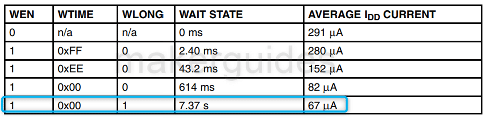
The above image gives you an idea of how the different WAIT values, along with the WLONG bit, can help you bring down the average supply current of the sensor to almost the same as the standby current!
In the next sections, let’s see the pinout of the RGB color sensor followed by the connection guide.
Features of the TCS34725 RGB Color Sensor
Here are the key features of the TCS34725 color sensor summarized in a table:
| Parameter | Range |
| Supply current (Active) | 330 uA (maximum) |
| Sleep current | 10 uA (max) |
| ADC integration step size | 2.56 ms |
| ADC count per step | 1024 counts |
| ADC count value (max) | 65535 counts |
| Wait step size | 2.4 ms |
| I2C clock frequency | 400 kHz |
| Supply voltage | 2.7 V to 3.6 V |
| Operating temperature | -30 ℃ to 70 ℃ |
Applications of the TCS34725 RGB Color Sensor
There are many different applications for the TCS34725 RGB color sensor, including:
- Consumer Electronics: The TCS34725 sensor is an excellent candidate to use where you can sense the ambient light available and set the screen brightness or screen mode (regular / night mode) automatically.
- Automotive industry – You can use the sensor to set the programmable lights to match the garage or the background location where the vehicle is.
- Healthcare – You can use the RGB color sensor TCS34725 to monitor the color of the test fluids such as urine and blood for automated faster diagnosis.
- Food processing – Fry till onions turn golden brown! The sensor can help you sense that. It can also help you to sort the fruits based on their color (ripe or not)
- Robotics – you can use color coding and ask robots to perform dedicated tasks based on the color code on the device / Box.
What are you using the sensor for? Let me know in the comments section below.
Pin Definition of RGB TCS34725 Color Sensor
The image below gives the top view of the IC TCS34725 with the pin details.
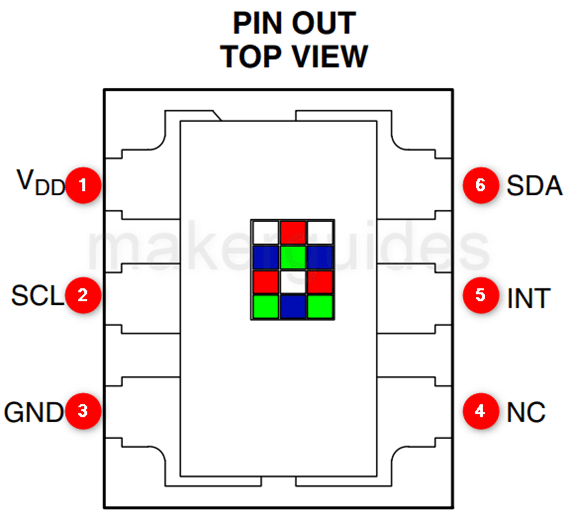
The following table provides the pin details of the TCS34725 color sensor.
| Pin Number | Pin Name | Pin Function |
| 1 | VDD | Power supply voltage |
| 2 | SCL | I2C Clock line for I2C serial communication |
| 3 | GND | Ground |
| 4 | NC | No connect – Don’t connect anything to this pin. |
| 5 | INT | Interrupt – Open drain (active low) |
| 6 | SDA | I2C data line for I2C serial communication |
How To Connect The TCS34725 RGB Color Sensor Module with ESP32
Now, I will show you how to build a project using an ESP32 and the RGB color sensor TCS34725. Let’s get started with the hardware connections.
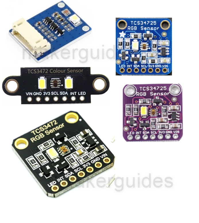
There are many variants available for the sensor boards. Since you are now well versed with the basics of the sensors and pinout definitions, there is no need to worry.
You will be confident in using the boards by following the connection guide. Let’s get started.
Step 1: Complete the hardware connections
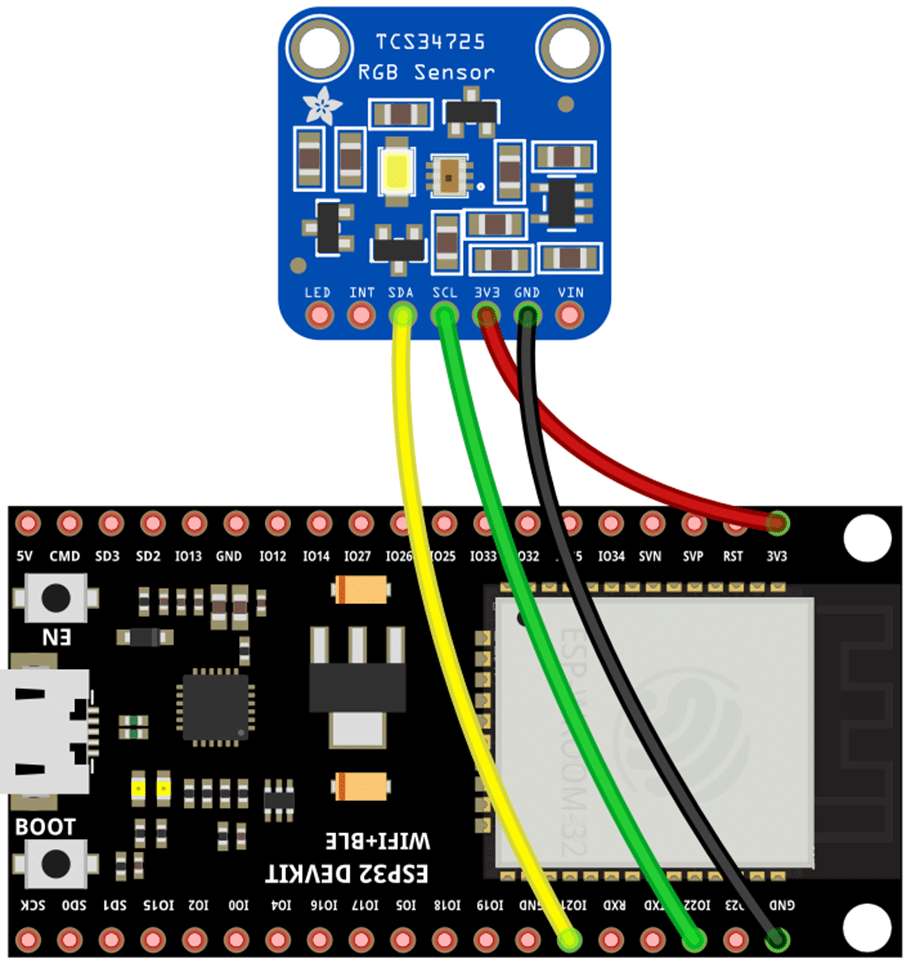
THe TCS34725 color sensor communicates over I2C. At the least, you need to connect power, ground, and I2C lines. The connections are also simple to understand and follow, as can be seen in the diagram above.
Always start with the ground connections. Power the entire system only after completing all the connections.
I am using GPIO21 and GPIO22 in my example. You can choose any other pins too. If you have to use different pins, edit the code accordingly.
The connection summary between the TCS34725 RGB color sensor and ESP32 is in the table below.
| SDA | I2C Data line |
| SCL | I2C Clock line |
| 3V3 | 3.3 V Power supply |
| GND | Ground Connections |
In the next step, we will program the ESP32 board.
Step 2: Program the ESP32 with the RGB sensor code below
Follow the next step to understand the code implementation. You can use the code below to test the ESP32 module and the connected RGB sensor module based on the TCS34725 color sensor.
Please follow our guide to install the ESP32 core on the Arduino IDE.
#include "Wire.h"
#include "Adafruit_TCS34725.h"
/*
  Connect SCL to analog 5
  Connect SDA to analog 4
  Connect VDD to 3.3V DC
  Connect GROUND to common ground */

/* Initialise with default values (int time = 2.4ms, gain = 1x) */
// Adafruit_TCS34725 tcs = Adafruit_TCS34725();

/* Initialise with specific int time and gain values */
Adafruit_TCS34725 tcs = Adafruit_TCS34725(TCS34725_INTEGRATIONTIME_700MS, TCS34725_GAIN_1X);

void setup(void) {
  Serial.begin(9600);

  if (tcs.begin()) {
    Serial.println("Found sensor");
  } else {
    Serial.println("No TCS34725 found ... check your connections");
    while (1);
  }

  // Now we're ready to get readings!
}

void loop(void) {
  uint16_t r, g, b, c, colorTemp, lux;

  tcs.getRawData(&r, &g, &b, &c);
  colorTemp = tcs.calculateColorTemperature(r, g, b);
  lux = tcs.calculateLux(r, g, b);

  Serial.print("Color Temp: "); Serial.print(colorTemp, DEC);
  Serial.print(" K - ");
  Serial.print("Lux: "); Serial.print(lux, DEC); Serial.print(" - ");
  Serial.print("R: "); Serial.print(r, DEC); Serial.print(" ");
  Serial.print("G: "); Serial.print(g, DEC); Serial.print(" ");
  Serial.print("B: "); Serial.print(b, DEC); Serial.print(" ");
  Serial.print("C: "); Serial.print(c, DEC); Serial.print(" ");
  Serial.println(" ");
}
Step 3: Code Walkthrough for the TCS34725 Color Sensor
Let’s walk through the code. This example is for the TCS34725 RGB color sensor. You start the code by including the wire library for I2C communication and TCS34725 library from Adafruit.
You can further build your project upon this code to either count or classify the objects that control the relay modules based on the value read by the color sensors.
(Think about sorting the tomatoes 🍅 between ripened and a not ripen ones)
#include "Wire.h"
#include "Adafruit_TCS34725.h"
There are two ways to initialize the color sensor: with default values (integration time of 2.4 ms and gain of 1x) or specific integration time and gain values.
The latter method is used in this code, with an integration time of 700 ms and a gain of 1x.
void setup(void) {
  Serial.begin(9600);

  if (tcs.begin()) {
    Serial.println("Found sensor");
  } else {
    Serial.println("No TCS34725 found ... check your connections");
    while (1);
  }

  // Now we're ready to get readings!
}
In the setup() function, the serial communication is initialized at a baud rate of 9600. Then, the tcs.begin() function is called to initialize the color sensor. The message “Found sensor” is printed on the serial monitor if the sensor is found.
Otherwise, the message “No TCS34725 found … check your connections” is printed, and the program is stuck in an infinite loop.
while (1);
Needs a reset after checking the wiring.
In the loop() function, the color sensor readings are obtained by calling the
tcs.getRawData(&r, &g, &b, &c) function, which stores the red, green, blue, and clear values in variables r, g, b, and c, respectively.
Next, you calculate the color temperature and the lux values: using the tcs.calculateColorTemperature(r, g, b) and tcs.calculateLux(r, g, b) functions, respectively.
Finally, the color temperature, lux, red, green, blue, and clear values are printed to the serial monitor.
I hope the RGB color sensor TCS34725 code explanation helped.
FAQ About The RGB Sensor TCS34725
I have included a list of the most frequently asked questions about the color sensor TCS34725.
What is the communication interface used by the TCS34725?
You can use the I2C interface to communicate with the sensor. The sensor supports fast mode (up to 400 kbits/s ).
What is the operating voltage range of the TCS34725 Color sensor?
The TCS34725 operates within a voltage range of 2.7 V to 3.6 V. If the I2C bus is pulled up to 1.8 V, the maximum voltage is 3.3 V.
What is the spectral response of the TCS34725?
The spectral response of the sensor is similar to the human eye.
Please refer to the Fundamentals section in this article to know more about color sensitivity and other exciting information about the sensor.
What is the resolution of the TCS34725?
The TCS34725 has a resolution of 16 bits per channel, allowing for a total of over 16 million different color combinations. Every color has a dedicated ADC followed by the photo sensor. In addition to the RGB bits, you also have 16 bits of information on the clear light as well.
What applications is the TCS34725 used for?
The TCS34725 is used in color sensing and ambient light sensing applications. To understand why the TCS3725 sensor is such a good fit, please refer to the basics section of this article.
- Health/fitness products
- Ambient light sensing (to set TV brightness automatically, for example)
- Industrial process control (to monitor the quality of products based on color)
- Medical diagnostics automation and more.
Is the TCS34725 compatible with ESP32?
Yes, the TCS34725 is fully compatible with ESP32. You don’t have to use level shifters. The sensor may be more compatible with ESP32 than an Arduino UNO (my opinion).
Conclusion
This article has covered all the essential information about the RGB sensor TCS34725, including how it works, the pin details, register information, key features and applications.
Knowing detailed information about the sensors helps you decide on and build more powerful projects using the TCS34725 sensor.
I also shared an ESP32 connection guide and some example code with explanation, which you can use to test and adapt to your own projects.
If you have further questions about the sensors, please post them in the comments section.
I’d love to hear from you! Let us know if there’s anything else you’d like me to cover in future articles.

I am Puneeth. I love tinkering with open-source projects, Arduino, ESP32, Pi and more. I have worked with many different Arduino boards and currently I am exploring, Arduino powered LoRa, Power line communication and IoT.