In this article, I will show you how to use relay modules with an ESP32 microcontroller.
Relay modules are needed to control high-voltage devices such as AC lamps, motors, and fans.
Relays are basically electromechanical switches. They can be operated with a low voltage; on the other side, you can control appliances powered by AC central (120 V or 230 V).
You see the relays used in smart home circuit boards, automatic person detection circuits, alarm circuits and more.
In this article, I will teach you all the fundamental aspects of a relay and how to control a relay using an ESP32.
I share a connection guide and working ESP32 code to control the relay.
By the end of this article, you will understand how to use a relay, and how to watch the relay parameters in your next big project.
Let’s get started!
Components Needed To Build ESP32 And Relay Modules Project
Hardware Components
- ESP32 Wroom 2.4 GHz with integrated Antenna x 1
- ESP32 compatible 3 V Relays x 1
- Dupont wire x 1 set
- Micro USB Cable for ESP32 (for powering ESP32 and programming) x 1
Software
Guide
Fundamentals Of The Relays
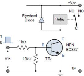
A relay is an electrically driven switch. Similar to how we push to operate a mechanical switch, we need to provide a small voltage to operate a relay.
Below you see one example of driving a relay circuit using a transistor. You can drive the transistor using an ESP32 or an Arduino UNO GPIO pin to turn the relay ON or OFF.
How Does A Relay Work?
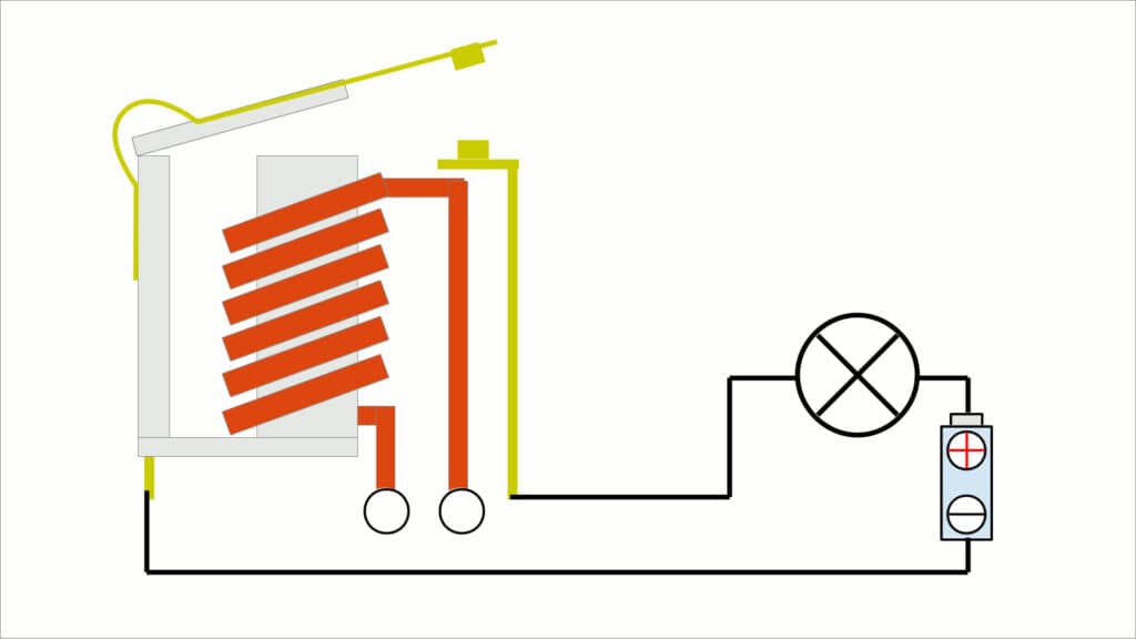
A relay works based on the electrically induced magnetic field. When the current passes through a coil, it creates a magnetic field around it.
You use this principle to attract or push away the lever, to make or break the connection on the switching side.
Based on the number of poles and throws, there are different types of relays.
What is a pole and a throw?
The number of poles corresponds to the number of electrical loads a single switch controls in one action. The number of throws is the number of contacts possible in the relay.
You will understand better in the following few paragraphs about poles and throwing clearly.
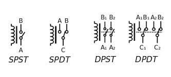
The four common types of relays are
- SPST – Single Pole Single Throw relay
- SPDT – Single Pole Dual Throw relay
- DPDT – Dual Pole Dual Throw relay
- SPDT – Dual Pole Dual Throw relay
Let’s quickly have a look at each type:
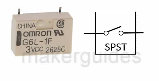
SPST relay
SPST – It has only one contact. It will be either NC or NO. It has two terminals. It will simply make or break a connection. It is a very close representation of wall switches.
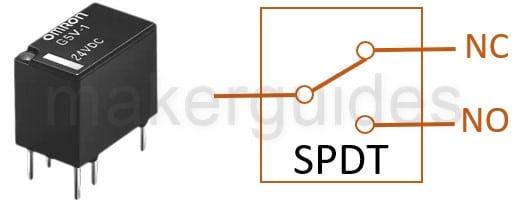
SPDT relay
SPDT – It has only one pole but two contact options: NC and NO. NC is a normally closed terminal, and NO is normally an open terminal.
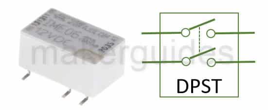
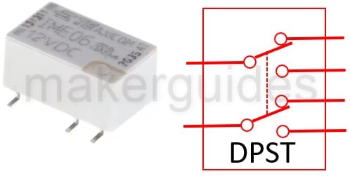
DPST relay
The DPST relay is a combination of two SPST relays. You can find DPST relay helpful when you want to drive two loads together (Example: Lights and fan once you detect the human presence.)
DPDT relay
The DPDT relay stands for Double Pole Double Throw relay. You can use the DPDT relay to connect or disconnect two circuits together.
You can always think of DPDT as two SPDTs in parallel and operating together.
I will take you through the important characteristics of the relay in the coming section.
Features of a Relay (Example)
Here are the features of the relay summarized in a table. You can find the relay datasheet here.
| Parameter | Range |
| Nominal Coil voltage | 3.3 V |
| Max coil voltage | 4 V |
| Coil resistance | 70 Ohms |
| Operate voltage | 2.5 V ( must operate by) |
| Release voltage | 0.4 V (must release by) |
| Switching voltage | 100 V max |
| Switching current | 250 mA |
| Carry Current | 500 mA |
| Contact rating | 3 W |
| Life expectancy | 1000 Million operations |
| Contact resistance | 125 mOhms |
| Insulation resistance | 10 GigaOhms |
| Dielectric strength (VDC) | 200 V |
| Operate time | 250 us |
| Release time | 50 us |
It is crucial to understand the relay parameters. In the following sections, I will teach you the parameters of the relays.
If you choose the wrong relay, the project may not be stable, can create a fire hazard, or may only work intermittently.
Nominal Coil voltage
This is the coil voltage needed to operate the coil. It is a low-voltage range input. Usually, an ESP32 GPIO can directly drive the coil input pin.
Max coil voltage
You should not apply a voltage that is above the max coil voltage. This will permanently damage the coil.
Coil resistance
Every relay will have a coil that will be driven when activated. You can calculate the power dissipated across the coil using the resistance and voltage across the coil. It will give an idea about the current ability of the source power needed to drive the relay.
Operate voltage
Minimum voltage to be applied across the coil to make the relay activated.
Release voltage
The maximum voltage across the coil at which the relay will deactivate.
Switching voltage
Maximum voltage at the load terminal the relay can support. If you are planning to drive a bulb at 120 V using a relay, then the relay switching voltage rating should be at least more than 150 V.
Switching Current
Maximum current supported to drive the load.
Life expectancy
Every relay has an expiry date. We mention several operations. Most relays can live for more than 1 million operations (ON / OFF). You should understand the use case and estimate the relay life accordingly.
Operate time
Time taken by the coil to get magnetized (once activated) and move the arm to the other contact. It will usually be in ms.
Release time
A finite time is taken by the coil to de-energize and the magnetic field to collapse so that the relay is turned off. It is called release time. It will be in ms.
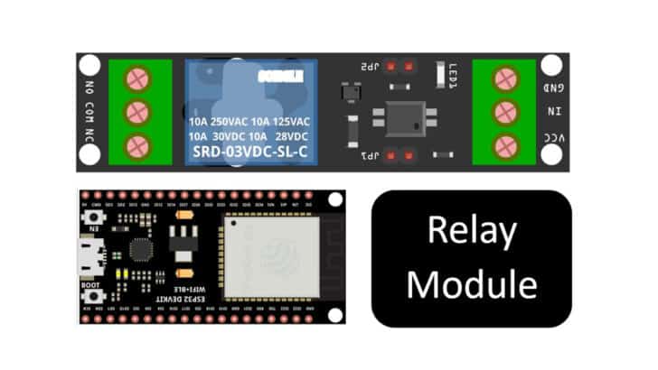
Pin definition of Relay module
⚠️ Be cautious with relay connections. Most of the time, relays switch high voltages. You should take sufficient care and guidance before working with high voltages. High voltages can kill you!
Please refer to the datasheet of the module you are using before you continue with the connections.
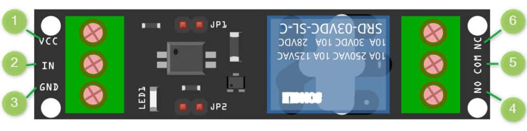
You can use the below reference table to quickly refer to the pinouts of the relay module pin details:
| Section | Pin Name | Pin Function |
| Low voltage section (safe to use) | VCC | Power supply for low voltage section. Usually, 3.3 V or 5 V is needed. |
| IN | Control pin. In our module, this pin can be either 3.3 V or GND. You can turn on the relay by sending 3.3 V on this pin using ESP32 GPIO. To turn it off, send a 0. | |
| GND | Ground connection | |
| High Voltage section ⚠️ | NC | Normally connected – When the Relay is OFF, this pin is connected to the COM pin |
| COM | Common pin for both NC and NO pin configuration | |
| NO | Normally Open – When the relay is OFF, this pin is disconnected from the COM pin |
Applications of Relays
Lighting Control: Motion sensors use relays to control the light when they detect motion. Relays are extensively used in homes and buildings to control the lights automatically using ESP32 or similar smart controllers.
Motor control: Relay helps you easily control high voltage, high power motors using a low-power microcontroller such as Arduino UNo or an ESP32. Motors are used in appliances (Dishwashers, washing machines, etc.), industrial machinery, and vehicles too!
Power Supply systems: Relays are used in battery charging applications to make or break contacts automatically based on battery charge status.
Automation: Relays find a wide range of applications in industrial automation.
Programmable logic controllers are controlled using reality in assembly lines, sorting facilities, manufacturing, and packing.
Automotive: Heard of a tick-tick sound when you turn your vehicle with a turn indicator? It is the sound of the relay switching the lights on and off. Relays also control starter motors, fuel pumps, and headlights.
Relays are also used in oscilloscopes, where it tries to switch the internal impedance to match the user settings. Relays are also used to manage signal routing in measurement equipment.
Alexa and Google Nest based smart systems also use relays in the smart modules to make or break contact using smart plugs.
HVAC – Relays control water flow (for room heating) in heating, ventilation, and air conditioning.
These are just a few examples. What are you using the relay for? Let me know in the comments section below.
Next, let’s connect an ESP32 to a relay module.
Instructions To Connect The Relay Module With ESP32
I will show you how to build a project using ESP32 and the Relay Module. Let’s get started with the hardware connections.
Step 1: Complete the hardware connections
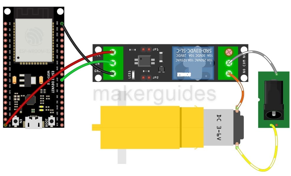
Imagine you are driving a DC motor connected to the relay module. My DC motor is powered from 6 V (using the jack). Note that you cannot drive the motor directly using ESP32. Because the ESP32 cannot supply 6 V, nor can it support the current required by the motor.
The connections are simple to understand and follow, and are demonstrated in the image above.
Always start with the ground connections. Power the entire system only after completing all the connections.
I am using GPIO34 in my example. You can choose any other ADC pin. If you have to use other pins, edit the code accordingly.
Here is the summary of connections between the relay module and the ESP32 pin.
- Connect the GND pins of both ESP32 and the relay module together.
- Connect the GPIO34 pin of the ESP32 to the IN pin of the relay module.
- Connect the relay module’s VCC pin to the 5 V pin of the ESP32.
Step 2: Program the ESP32 with the code below
Follow the next step to understand the code implementation. You can use the code below to test the ESP32 and connected relay module. Please follow our guide to install the ESP32 core on the Arduino IDE.
/*
  Turns a Motor on for five seconds, then off for five seconds, repeatedly.
*/


# define MOTOR_PIN 17

//The setup function runs once when you press reset or power the board
void setup() {
  // initialize digital pin MOTOR_PIN as an output.
  pinMode(MOTOR_PIN, OUTPUT);
  Serial.begin(9600);
}


// the loop function runs over and over again forever
void loop() {
  digitalWrite(LED_BUILTIN, HIGH);   // turn the Motor on (HIGH is the voltage level)
  Serial.println("Turning ON motor");
  delay(5000);                       // wait for 5 seconds
  Serial.println("Turning ON motor");

  digitalWrite(LED_BUILTIN, LOW);    // turn the Motor off by making the voltage LOW
  Serial.println("Turning OFF motor");
  delay(5000);                       // wait for 5 seconds
}
Step 3: Code Walkthrough
Let’s walk through the code. This example tests a relay module connected to GPIO17 of the ESP32 module. The code is used to turn on and off a motor.
You can use this code for controlling a motor connected to pin 17 of an ESP32 board. It turns the motor on for 5 seconds and then turns it off for 5 seconds repeatedly.
# define MOTOR_PIN 17
The setup() function is called once when the board is powered on or reset. In this function, pin 17 is initialized as an output pin using the pinMode() function.
pinMode(MOTOR_PIN, OUTPUT);
The Serial.begin() function is called to initialize serial communication with the computer at a baud rate of 9600.
Serial.begin(9600);
In the loop() function, I am using the digitalWrite() function to turn the motor on by setting the voltage level of pin 17 to HIGH.
A message is also printed on the serial monitor to indicate that the motor is being turned on. It is optional. You can skip this if you want. We then wait for 5 seconds using the delay() function.
delay(5000); // wait for 5 seconds
Next, the digitalWrite() function is used to turn the motor off by setting the voltage level of pin 17 to LOW. and waiting for another 5 seconds using the delay() function.
The loop() function repeats this process indefinitely, causing the motor to turn on and off every 5 seconds.
FAQs About The Relays and ESP32 Projects
I have included a list of the most frequently asked questions about projects built using the ESP32 and the relay modules.
What is a relay?
A relay is an electrical switch that is controlled by an electrical signal. It switches high-voltage or high-current circuits on or off using a low-voltage or low-current signal.
For example, you can use ESP32’s 3 V GPIO pin to control an AC motor on mains voltage!
How does a relay work?
A relay uses an electromagnet to move a set of contacts from one position to another. When a current flows through the coil of the electromagnet, it creates a magnetic field that pulls the contacts closed or pushes them open, depending on the type of relay.
There are also semiconductor relays where there are no moving contacts. Electromechanical relays are found more easily everywhere.
What are the types of relays?
There are several relays, including electromechanical, solid state, reed, and thermal relays. Electromechanical relays are the most common and are widely used in industrial and automotive applications.
You might be familiar with the switching sound of the relay. It is primarily an electromechanical relay.
What are the applications of relays?
Relays are found in various applications, including controlling lighting and motors, switching power supplies, controlling heating and cooling systems, and protecting circuits from overcurrents.
Please refer to the applications section above for a comprehensive list of applications that you find relay useful.
How do I choose a relay for my application?
When selecting a relay for your application, you should consider factors such as the required voltage and current rating, the switching speed, the expected lifespan of the relay, and the environmental conditions in which it will be used.
For more details, jump to the fundamentals section of this article.
How do I wire a relay?
The wiring of a relay depends on the specific relay and application. Generally, you connect the load between the COM pin and the NO pins. It really depends on your end use case.
On the ESP32 front, make sure the relay can be operated with a 3 V supply. If not, ESP32 GPIO cannot be directly connected to the relay’s control input pin.
Conclusion
In this article I have covered the relay application and how to use the relay with an ESP32 microcontroller.
I shared details on how a relay works and information on how to choose a relay for your particular situation, as well as some common applications where they may be used.
I have also walked you through how to make the wiring connections and shared some example code for ESP32.
I have used relays to control water motors for innovative automation projects. Relays are your best friend if you know the basics as they enable you to control higher voltage appliances.
If you have suggestions to improve the article, please share your feedback below, and let us know if there’s anything else you’d like me to cover in future articles.

I am Puneeth. I love tinkering with open-source projects, Arduino, ESP32, Pi and more. I have worked with many different Arduino boards and currently I am exploring, Arduino powered LoRa, Power line communication and IoT.