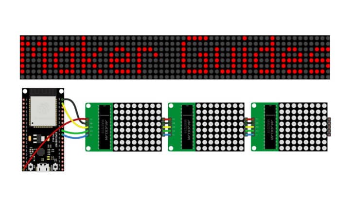
In this article, I will show you how to connect a MAX7219 LED dot matrix display driver with an ESP32 system.
The MAX7219 driver is a very easy-to-use integrated circuit (IC), and connecting that to an ESP32 provides you with a wireless display project.
I will teach you how to connect the two devices and share some example code that you can use.
I will show you all the valuable features of the MAX7219 and I’ve also explained all the tricks and hacks to get the best out of the IC.
By the end of this article, you will have an understanding of how the ESP32 and MAX7219 work, and the skills and knowledge to begin experimenting and building your own projects.
Whether you’re a beginner or an experienced maker, this article will provide a solid foundation to explore the exciting world of LED dot matrix displays.
Let’s get started!
Components Needed To Build ESP32 And MAX7219 LED Driver
Hardware Components
- Dupont wire x 1 set
- Micro USB Cable for ESP32 (for powering ESP32 and programming) x 1
Software
Guide
Makerguides.com is a participant in the Amazon Services LLC Associates Program, an affiliate advertising program designed to provide a means for sites to earn advertising fees by advertising and linking to products on Amazon.com.
Basics of The ESP32 And MAX7219 LED Driver
In this section I will cover the fundamentals of the MAX7219 LED driver and describe the pin connections.
MAX7219 LED Driver IC Features
Here are the main features of the MAX7219 IC:
- 10 MHz Serial Interface
- Individual LED Segment Control
- Decode/No-Decode Digit Selection
- 150 μA Low-Power Shutdown (Data Retained)
- Digital and Analog Brightness Control
- Display Blanked on Power-Up
- Drive Common-Cathode LED Display
- Slew-Rate Limited Segment Drivers for Lower EMI (MAX7221)
- SPI, QSPI, MICROWIRE Serial Interface (MAX7221)
- 24-Pin DIP and SO Packages
MAX7219 Fundamentals
Now I will take you through all the details you would need to know to make the best of MAX7219 IC.
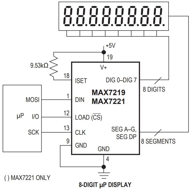
The above image represents the basic connection diagram you must rig up to use the MAX7219 to drive a seven segment display.
You need three pins from your MCU (in this case, ESP32 pins) to communicate with the LED driver IC.
The three pins are DIN, LOAD, and CLK.
DIN – This is the MAX7219’s data input pin. You have to send the data serially into this pin. The MAX7219 accepts data on this pin on every rising edge of the clock. You will send in 16 bits of serial data.
LOAD – Load pin latches the data received on the data pins.
CLK – The Clock pin is the third pin needed to complete the connections between the ESP32 and the LED driver IC.
During the rising edge of the clock, the data on the DIN pin pushes the data into the internal shift register. During the falling edge of the CLK signal, the data comes out on the DOUT signal.
There are ready-made libraries that will help you to handle the required communication easily. You will learn about that in the following sections.
What is DOUT pin?
DOUT pin on the MAX7219 is only needed when you cascade more than one MAX7219 ICs together.
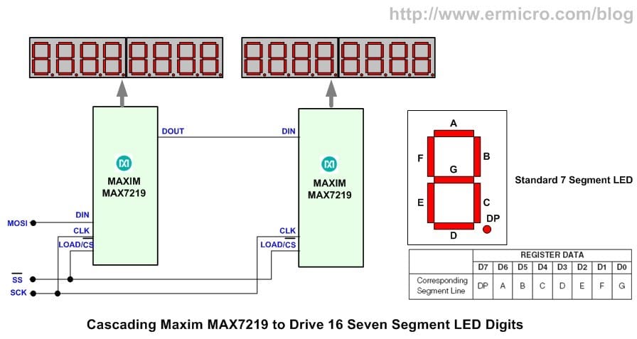
As shown in the above image, you can scale up the number of LEDs that can be driven using the MAX7219.
Another image represents the connection guide cascading two display modules.
Here you send the data on the DIN pin of the first IC. After 16 bits of data, the 17th data bit will be sent out on the DOUT pin of the first IC.
It would be best if you connected the DOUT pin of the first IC to the DIN pin of the second IC.
MAX7219 Pin Description
In the table below, I will describe all the MAX7219 pins.
| Pin Number | Pin Name | Pin Function |
| 1 | DIN | Serial Data Input |
| 2,3, 5-8, 10, 11 | DIG 0 to DIG 7 | Eight Digit drive lines that sink current from the display common cathode. (8 pins) |
| 4, 9 | GND | Ground pin. Connect GND pins together |
| 12 | LOAD | Load-Data Input. The last 16 bits of serial data are latched on LOAD’s rising edge |
| 13 | CLK | Serial-Clock Input. 10MHz maximum rate. Data is shifted into the internal shift register on CLK’s rising edge. On CLK’s falling edge, data is clocked out of DOUT. On the MAX7221, the CLK input is active only while CS is low |
| 14-17, 20-23 | SEG A-SEG G, DP | Seven segment and decimal point drive that source the current to the display. DP stands for decimal point |
| 18 | ISET | Connect to VDD through a resistor (RSET) to set the peak segment current. More details are in the coming sections below. |
| 19 | V+ | Positive Supply Voltage. Connect to 5 V |
| 24 | DOUT | Serial Data output. The data into DIN is valid at DOUT 16.5 clock cycles later. Used in the daisy chaining of several MAX7219 driver ICs |
What is the function of the ISET pin on the MAX7219 LED Driver?
The ISET pin sets the LED current limit for the LEDs. Every LED needs a current limiting component. If you don’t limit the current through the LED, it will eventually heat up and burn out.
Conventionally you limit the current through the LED using series resistors. But, while you’re using MAX7219 IC, you can efficiently limit the current.
Here is how you set the current limit:
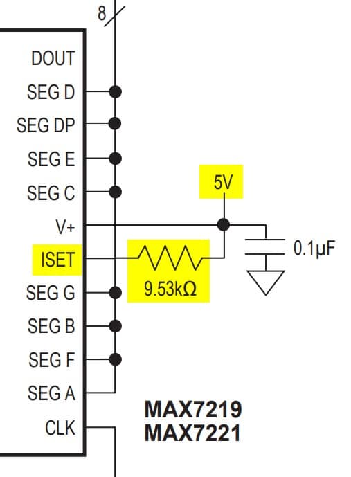
The ISET parameter is used to set the current limit for the SEG pins (LEDs). Connect the resistor between 5 V and the ISET pin to program the current limit.
The current limit is not an accurate one.
As a rule of thumb, the LED current will be 100 times the current flowing into the ISET pin.
Example of how to set the LED current in MAX7219
Let’s say we want to set 20 mA per LED. As per the rule of thumb above, the current through the ISET must be 100 times lower than the expected LED current.
- Expected LED Current → 20 mA
- 1/100th time of the LED current → 20 mA / 100 = 0.2 mA or 200 µA.
Resistance = Voltage / Current
RISET = 5 V / 200 µA = 25 kOhms
If you do not want to take too much trouble to calculate the resistance, you can use the below link to use an online calculator (safe and easy).
Link: https://www.calculator.net/ohms-law-calculator.html
Here is a screenshot of an example calculation:
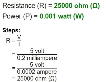
Conclusion: Connect a 25 Kohms resistor between the ISET pin and 5 V to set the LED current to 20 mA.
Okay. Now, what if you want to dim the LEDs?
How to control the LED brightness in the 7-segment LEDs?
Should you change the resistor value every time? No.
The MAX7219 IC allows brightness control of the LEDs connected to the SEG pins. The maximum brightness will be the set current using ISET.
There is a register called the internal register which will control the display brightness using the internal pulse width modulator. You can control the brightness at 32 levels.
In the table below, you will learn about all the registers present in the MAX7219 chip.
| Register | Hex code | Function |
| No-Op | 0xX0 | The no-op register is used when cascading MAX7219s. . Connect all devices’ LOAD/CS inputs together and connect DOUT to DIN on adjacent devices. DOUT is a CMOS logic-level output that easily drives the DIN of successively cascaded parts. Basically, you use this when you want to send data to a particular MAX7219 in a cascade of MAX7219 ICs. |
| Digit 0 | 0xX1 | Digit 0 data |
| Digit 1 | 0xX2 | Digit 1 data |
| Digit 2 | 0xX3 | Digit 2 data |
| Digit 3 | 0xX4 | Digit 3 data |
| Digit 4 | 0xX5 | Digit 4 data |
| Digit 5 | 0xX6 | Digit 5 data |
| Digit 6 | 0xX7 | Digit 6 data |
| Digit 7 | 0xX8 | Digit 7 data |
| Decode Mode | 0xX9 | Used to set Decode BCD mode ON or OFF. It is helpful when you are driving seven segment display. When you are driving LEDs, you can disable them. |
| Intensity | 0xXA | The MAX7219 allows display brightness to be controlled with an external resistor (RSET) connected between V+ and ISET. The peak current sourced from the segment drivers is nominally 100 times the current entering ISET. |
| Scan Limit | 0xXB | Here, you can set the number of digits you are driving One IC can drive up to 8 7 segment digits. |
| Shutdown | 0xXC | Control the power mode to be the active mode or shutdown mode. Use Shutdown mode to save power. |
| Display test | 0xXF | All LEDs can be turned On at once. Helpful in testing at the production site. Isn’t it? |
An example connection diagram is where you can drive 16 segment display modules.
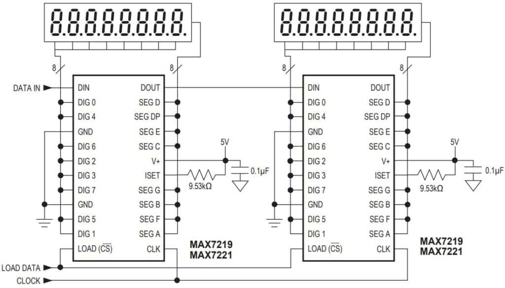
Notice that the clock signal is standard, as well as the load signal. The Data enters the DIN pin of the first module.
The DOUT pin of the first module is connected to the DIN of the second module. That’s cascading.
If you have further questions or need help, I will gladly help you in the comments section below.
Instructions To Connect The MAX7219 Module with ESP32
I will show you now how to build a project using ESP32 and the MAX7219 LED Driver.
Let’s get started with the hardware connections.
Step 1: A quick look at the MAX7219 Module
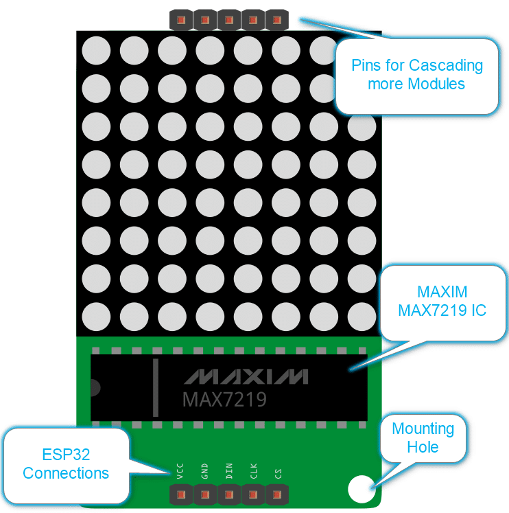
A close up image of the connector here

Let’s see the connections needed to program the module using ESP32.
Step 2: Connect the MAX7219 Module to ESP32
Follow the diagram above to complete the connection between the MAX7219 and ESP32 modules.
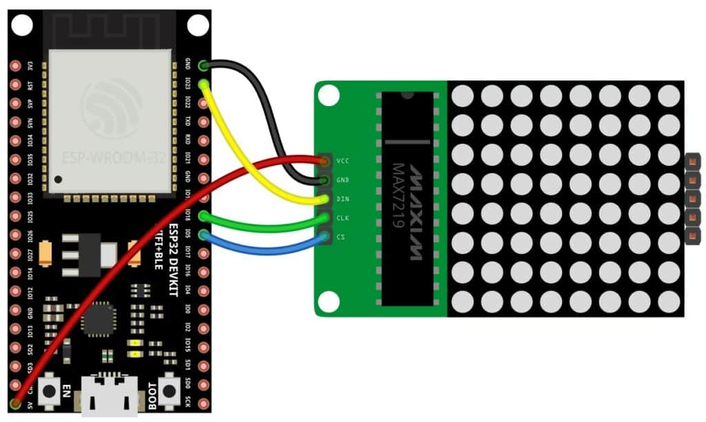
This table provides a summary of the connections between the two devices:
| ESP32 | MAX7219 Module |
| 5V | VCC |
| GND | GND |
| GPIO18 | CLK |
| GPIO5 | CS |
| GPIO23 | DIN |
If you have further questions or need help, I will gladly help you in the comments section.
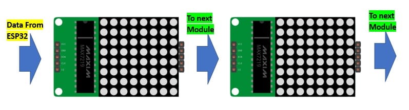
Step 3: Cascading multiple MAX7219 (three in this example)
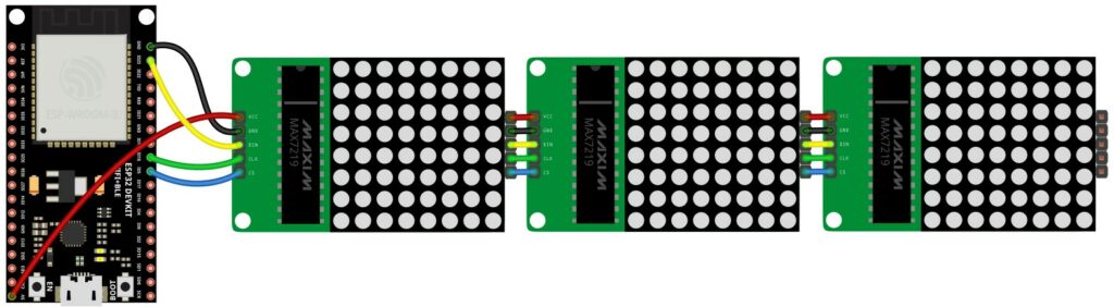
As mentioned earlier in this article, you can cascade multiple LED displays by connecting them as in the image here.
Step 4: Connect Power Source
You can connect the power once you have completed programming the ESP32 provided in the next section.
Congratulations on completing the hardware connections.
Step 5: Example Code to program ESP32 to communicate with MAX7219
You can use the code below to test the ESP32 module and the connected MAX7219 LED driver.
Please follow our guide to install the ESP32 core on the Arduino IDE.
#include <MD_Parola.h>
#include <MD_MAX72xx.h>
#include <SPI.h>

// Uncomment according to your hardware type
#define HARDWARE_TYPE MD_MAX72XX::FC16_HW
//#define HARDWARE_TYPE MD_MAX72XX::GENERIC_HW

// Defining size, and output pins
#define MAX_DEVICES 3
#define CS_PIN 5

MD_Parola Display = MD_Parola(HARDWARE_TYPE, CS_PIN, MAX_DEVICES);

void setup() {
  Display.begin();
  Display.setIntensity(0);
  Display.displayClear();
}

void loop() {
  Display.setTextAlignment(PA_LEFT);
  Display.print("ESP32");
  delay(2000);

  Display.setTextAlignment(PA_CENTER);
  Display.print("ESP32");
  delay(2000);

  Display.setTextAlignment(PA_RIGHT);
  Display.print("ESP32");
  delay(2000);

  Display.setTextAlignment(PA_CENTER);
  Display.setInvert(true);
  Display.print("ESP32");
  delay(2000);

  Display.setInvert(false);
  delay(2000);
}
Code Explanation:
Let’s walk through the code. You can use the code below to test the ESP32 and a cascaded connection of three MAX7219 with LED matrix modules.
#include <MD_Parola.h>
#include <MD_MAX72xx.h>
#include <SPI.h>
These are the library headers included in the program. The MD_Parola and MD_MAX72xx libraries control the display, while the SPI library is used for communication over the SPI bus.
#define HARDWARE_TYPE MD_MAX72XX::FC16_HW
In this case, the FC16 hardware is being used.
#define MAX_DEVICES 3
#define CS_PIN 5
These two lines define the maximum number of display devices and the PIN for the chip select line. Three displays are used, and the chip select line is connected to pin 5 of ESP32.
MD_Parola Display = MD_Parola(HARDWARE_TYPE, CS_PIN, MAX_DEVICES);
This line creates an instance of the MD_Parola class named Display. The constructor of the MD_Parola class is called with the HARDWARE_TYPE, CS_PIN, and MAX_DEVICES values.
void setup() {


  Display.begin();
  Display.setIntensity(0);
  Display.displayClear();
}
This is the setup function, which is called once when the program starts.
The Display.begin() function initializes the display, the Display.setIntensity(0) sets the display intensity to 0 (i.e., the display is off), and the Display.displayClear() function clears the display.
In the loop() function, The Display.setTextAlignment() function is used to set the text alignment to either left, centre, or right. The Display.print() function prints the text “ESP32” to the display.
After each text is printed, the program waits 2 seconds using the delay() function. Then, the text alignment is changed, and the text is printed again. This is repeated for left, centre, and right alignment.
Next, the text alignment is set to the centre again, and the display is inverted (white text on black background) using the Display.setInvert(true) function. The text “ESP32” is printed again, and the program waits for 2 seconds.
The display is then reverted back to its original state using Display.setInvert(false), and the program waits for another 2 seconds before starting the loop over again.
I hope this explanation helps! Let me know if you have any other questions.
FAQs About The ESP32 And MAX7219 LED Driver
I have included a list of the most frequently asked questions about projects built using the ESP32 and the MAX7219 driver. If you have more questions, please post them in the comments section.
I will be happy to answer them.
What is the MAX7219?
The MAX7219 is a versatile LED display driver that can control up to eight 7-segment LED displays or up to 64 individual LEDs. It is designed for microcontrollers and can communicate using a simple SPI protocol.
How does the MAX7219 work?
The MAX7219 works by receiving data from a microcontroller through the SPI protocol. It then uses this data to control the LED displays or individual LEDs connected to it. It can control the brightness and scanning rate of the LEDs, as well as detect and report errors. With a MAX7219 IC, controlling 64 LEDs will be a manageable task.
What is the maximum number of LED displays that the MAX7219 can control?
The MAX7219 can control up to eight 7-segment LED displays or 64 individual LEDs. It can also be cascaded with other MAX7219 chips to control more displays or LEDs. You can control a complete name label formed using MAX7219 modules.
What voltage does the MAX7219 require?
The MAX7219 can operate on various input voltages, typically between 4.0V and 5.5V. However, it can also handle voltages up to 10V in some cases. It is recommended to use a regulator if you need more clarification on the stability of the voltage supply. A 7805 regulator can provide stable 5 V under all conditions.
What is the difference between the MAX7219 and the MAX7221?
The MAX7221 is a higher-performance version of the MAX7219, with additional features such as a serially-controlled shutdown mode and an on-chip BCD-to-7-segment decoder. However, it is generally more expensive than the MAX7219. For most of the nobby projects, my first preference is always MAX7219.
How do I connect the MAX7219 to my microcontroller?
The MAX7219 communicates with a microcontroller using the SPI protocol, which requires four connections: data input (DIN), clock input (CLK), chip select (CS), and ground (GND). You can find detailed wiring diagrams and example codes in the sections above. If you still need further help, please feel free to comment. I will be glad to help you.
What are some typical applications for the MAX7219?
The MAX7219 is commonly used in applications that require the control of LED displays, such as digital clocks, scoreboards, and panel meters. It can also be used to create scrolling text displays or to control individual LEDs for decorative or signalling purposes.
Conclusion
In this article, I have covered all the essential information about the LED Driver MAX7219.
I have covered the crucial aspects that will help you get the best of MAX7219 chip features for your next project.
The connection guide and the working example code will help you to get started with your own project much faster.
If you have any questions about the LED Drivers, LEDs, the MAX7219 driver or ESP32, I will happily answer them in the comments section.
I’d love to hear from you! Let us know if there’s anything else you’d like me to cover in future articles.

I am Puneeth. I love tinkering with open-source projects, Arduino, ESP32, Pi and more. I have worked with many different Arduino boards and currently I am exploring, Arduino powered LoRa, Power line communication and IoT.