In this tutorial, I will give you all the necessary information about controlling the speed and direction of a DC motor with an L293D motor driver IC using an Arduino UNO board.
I have included a wiring diagram and details of Arduino code to control the DC motor by sending characters from Serial Monitor of Arduino IDE with multiple examples.
Supplies
Hardware components
| Arduino Uno Rev3 | × 1 | Amazon |
| USB cable type A/B | × 1 | Amazon |
| DC Gearbox Motor | × 1 | Amazon |
| L293D Driver IC | × 1 | Amazon |
| Breadboard | × 1 | Amazon |
| Jumper wires | × 15 | Amazon |
| Power supply (5V) | × 1 | Amazon |
Software
| Arduino IDE | Arduino_IDE |
Makerguides.com is a participant in the Amazon Services LLC Associates Program, an affiliate advertising program designed to provide a means for sites to earn advertising fees by advertising and linking to products on Amazon.com.
About Motor Driver IC L293D
The L293D is a quadruple high current half-H driver IC suitable for controlling DC motors. It can provide a bidirectional drive current up to 1 A at voltages from 4.5 V to 36 V. Below you can find the datasheet for the chip.
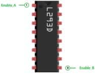
Pinout of the L293D IC
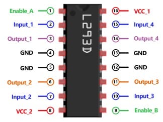
The L293D is a 16 pins motor driver IC, and you can control two DC motors or one stepper motor under 600mA current.
Power Supply Pins
Pin 8 (VCC_2) and 16 (VCC_1) are used to power up the L293D motor driver IC.
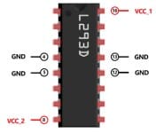
VCC_2 provides the power supply to the internal H-Bridge of IC, and it can be from 4.5V to 36V. VCC_1 is used for internal logic translation, and it should be 5 V. Pin 4, 5, 12, and 13 (GND) are the device ground and heat sink pins.
Direction Control Pins
Pin 2 (Input_1), Pin 7 (Input_2), and Pin 10 (Input_3), Pin 15 (Input_4) control the switches of the H-Bridge circuit inside the L293D IC.
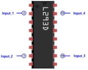
Input_1 and Input_2 have connected two terminals of DC motor_1used to control the direction of motor_1. Similarly, Input_3 and Input_4 are used to control the direction of motor_2.
I will use an Arduino UNO to generate direction signals for all Input pins, and based upon the level of these pins (High or Low) motor will run forward or backward.
You can see the details in the below table for motor direction control.
| Input_1 / Input_3 | Input_2 / Input_4 | Motor Direction |
| Low | Low | Break, Motor OFF |
| Low | High | Backward (Anti Clockwise) |
| High | Low | Forward (Clockwise) |
| High | High | Break, Motor OFF |
Speed Control Pins
The DC motors can be rotated at a specified speed as per the value set by Arduino UNO on Pin 1 (Enable_A) for Motor_1 and Pin 9 (Enable_B) for Motor_2.
Active High signal enables pin turn ON the driver channel of L293D IC, which allows running the full motor speed.
Active Low signal on enable pin turns OFF the driver channel of L293D IC, which will stop the motor. To control the speed of the DC motor, you need to send PWM signals on enable pin of L293D IC. Speed of DC motor will change as per the duty cycle of PWM signals.
The details are explained in the code section.
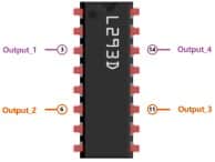
Motor Output Pins
The L293D motor driver IC provides output current up to 600mA to DC motor by Pin 3 (Output_1), Pin 6 (Ouput_2) for Motor_1 and Pin 11 (Output_3), Pin 14 (Output_4) for Motor_2.
DC Motor Specification
Voltage
A variety of DC motors are available in the market, rated from 3V to 100V; however, for robotic applications, 6V, 12V, or 24V DC motors are widely used. In this tutorial, we will consider 3V to 6V Gearbox DC motors.
Current
You need to select the DC motor with a maximum current rating of 600mA because above this current, the L293D driver IC will heat up and may get burned out.
Torque
Motor torque is an important factor when dealing with a load on the motor, and if you have an application where you need to put more load on the motor, you need to buy a motor with higher torque. Another way to increase the torque is to use a gearbox with a motor.
In this tutorial, I am using a DC motor with a gearbox with a gear ratio of 1:48.
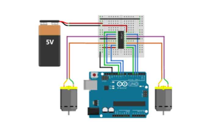
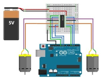
Wiring L293D motor driver IC with Arduino UNO
In this section, you will learn about the interfacing of the DC motors with the L293D drive IC and Arduino UNO board.
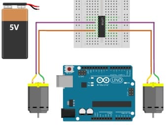
Step 1: Motors to L293D IC Connections
It would be best to start with the connecting motors wires to output pins of L293D IC.
Connect Motor_1 wires to Pin 3 (Output_1) and Pin 6 (Output_2) and Motor_2 wires to Pin 11 (Output_3) and Pin 14 (Output_4).
Step 2: Arduino UNO to L293D IC Connections
Now, Connect Arduino digital output Pin 10 and 9 to Pin 2 (Input_1) and Pin 7 (Input_2) of L293D for Motor_1.
Similarly, connect Arduino digital Pin 4 and 3 to Pin 10 (Input_3) and Pin 15 (Input_4) of L293D for Motor_2.
Furthermore, you need to provide PWM signals on Enable Pins for speed control of DC motors.
Connect PWM Pin 11 of Arduino UNO to Pin 1 (Enable_A) of L293d for Motor_1 and connect PWM Pin 5 of Arduino UNO to Pin 9 (Enable_B).
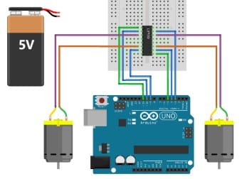
Step 3: Power supply to L293D IC Connections
Now you can provide a 5V supply to L293D IC by connecting Pin 8 (VCC_2) and Pin 16 (VCC_1) to 5V (Positive terminal of supply).
Connect all ground of IC to common ground on the breadboard.
All the connections are shown in the image.
Arduino Code – Controlling a DC Motor via Serial Terminal
If you want to test your DC motor, you should have control over it.
Following code allows you to control the speed and direction of both DC motors individually and simultaneously by sending characters from Serial Monitor of Arduino IDE.
You can copy the code by clicking on the button in the top right corner of the code field and uploading it to your Arduino UNO board.
Next, I will explain how the code works.
// Motor_1 Connection
#define ENABLE_1 11
#define MOTOR_1_A 10
#define MOTOR_1_B 9

// Motor_2 Connection
#define ENABLE_2 5
#define MOTOR_2_A 4
#define MOTOR_2_B 3

// other variables
char serial_data;
int speed_value_m1;
int speed_value_m2;

void setup() {
  Serial.begin(9600);
  Serial.println("Motor Init..");
  motor_1_init();
  motor_2_init();
  speed_value_m1 = 0;
  speed_value_m2 = 0;
}

void loop() {
  motor_speed_dir_control();
}

void motor_1_init() {
  pinMode(MOTOR_1_A, OUTPUT);
  pinMode(MOTOR_1_B, OUTPUT);
  pinMode(ENABLE_1, OUTPUT);

  digitalWrite(MOTOR_1_A, LOW);
  digitalWrite(MOTOR_1_B, LOW);
  analogWrite(ENABLE_1, LOW);
}

void motor_2_init() {
  pinMode(MOTOR_2_A, OUTPUT);
  pinMode(MOTOR_2_B, OUTPUT);
  pinMode(ENABLE_2, OUTPUT);

  digitalWrite(MOTOR_2_A, LOW);
  digitalWrite(MOTOR_2_B, LOW);
  analogWrite(ENABLE_2, LOW);
}

void motor_speed_dir_control() {
  while (Serial.available()) {
    serial_data = Serial.read();
    switch (serial_data) {
      case 's':
        analogWrite(ENABLE_1, 255);
        Serial.println("Enable Motor_1");
        break;
      case 'S':
        analogWrite(ENABLE_2, 255);
        Serial.println("Enable Motor_2");
        break;

      case 'h':
        analogWrite(ENABLE_1, 0);
        digitalWrite(MOTOR_1_A, LOW);
        digitalWrite(MOTOR_1_B, LOW);
        speed_value_m1 = 0;
        Serial.println("Stop Motor_1");
        break;
      case 'H':
        analogWrite(ENABLE_2, 0);
        digitalWrite(MOTOR_2_A, LOW);
        digitalWrite(MOTOR_2_B, LOW);
        speed_value_m2 = 0;
        Serial.println("Stop Motor_2");
        break;

      case 'f':
        digitalWrite(MOTOR_1_A, HIGH);
        digitalWrite(MOTOR_1_B, LOW);
        Serial.println("Motor_1 Forward Direction");
        break;
      case 'F':
        digitalWrite(MOTOR_2_A, HIGH);
        digitalWrite(MOTOR_2_B, LOW);
        Serial.println("Motor_2 Forward Direction");
        break;

      case 'b':
        digitalWrite(MOTOR_1_A, LOW);
        digitalWrite(MOTOR_1_B, HIGH);
        Serial.println("Motor_1 Backward Direction");
        break;
      case 'B':
        digitalWrite(MOTOR_2_A, LOW);
        digitalWrite(MOTOR_2_B, HIGH);
        Serial.println("Motor_2 Backward Direction");
        break;

      case 'a':
        for (int i = 0; i < 256; i++) {
          analogWrite(ENABLE_1, i);
        }
        Serial.println("Motor_1 acceleration");
        break;
      case 'A':
        for (int i = 0; i < 256; i++) {
          analogWrite(ENABLE_2, i);
        }
        Serial.println("Motor_2 acceleration");
        break;
      case 'd':
        for (int i = 255; i > 1; i--) {
          analogWrite(ENABLE_1, i);
          delay(5);
        }
        Serial.println("Motor_1 deceleration");
        break;
      case 'D':
        for (int i = 255; i > 1; i--) {
          analogWrite(ENABLE_2, i);
          delay(5);
        }
        Serial.println("Motor_2 deceleration");
        break;
      case 'i':
        if (speed_value_m1 <= 245) {
          speed_value_m1 += 10;
          analogWrite(ENABLE_1, speed_value_m1);
          Serial.println("Motor_1 increased Speed value: ");
          Serial.print(speed_value_m1);
        } else {
          Serial.println("Maximum Speed Limit Reached for Motor_1: ");
          Serial.print(speed_value_m1);
        }
        break;
      case 'I':
        if (speed_value_m2 <= 245) {
          speed_value_m2 += 10;
          analogWrite(ENABLE_2, speed_value_m2);
          Serial.println("Motor_2 increased Speed value: ");
          Serial.print(speed_value_m2);
        } else {
          Serial.println("Maximum Speed Limit Reached for Motor_2: ");
          Serial.print(speed_value_m2);
        }
        break;
      case 'r':
        if (speed_value_m1 >= 10) {
          speed_value_m1 -= 10;
          analogWrite(ENABLE_1, speed_value_m1);
          Serial.println("Motor_1 reduced Speed value: ");
          Serial.print(speed_value_m1);
        } else {
          Serial.println("Minimum Speed Limit Reached for Motor_1: ");
          Serial.print(speed_value_m1);
        }
        break;
      case 'R':
        if (speed_value_m2 >= 10) {
          speed_value_m2 -= 10;
          analogWrite(ENABLE_2, speed_value_m2);
          Serial.println("Motor_2 reduced Speed value: ");
          Serial.print(speed_value_m2);
        } else {
          Serial.println("Minimum Speed Limit Reached for Motor_2: ");
          Serial.print(speed_value_m2);
        }
        break;
      case 'X':
        digitalWrite(MOTOR_1_A, HIGH);
        digitalWrite(MOTOR_1_B, LOW);
        digitalWrite(MOTOR_2_A, HIGH);
        digitalWrite(MOTOR_2_B, LOW);
        analogWrite(ENABLE_1, 255);
        analogWrite(ENABLE_2, 255);
        Serial.println("Motor_1 and Motor_2 Forward Direction");
        break;
      case 'Y':
        digitalWrite(MOTOR_1_A, LOW);
        digitalWrite(MOTOR_1_B, HIGH);
        digitalWrite(MOTOR_2_A, LOW);
        digitalWrite(MOTOR_2_B, HIGH);
        analogWrite(ENABLE_1, 255);
        analogWrite(ENABLE_2, 255);
        Serial.println("Motor_1 and Motor_2 Backward Direction");
        break;
      case 'Z':
        digitalWrite(MOTOR_1_A, LOW);
        digitalWrite(MOTOR_1_B, LOW);
        digitalWrite(MOTOR_2_A, LOW);
        digitalWrite(MOTOR_2_B, LOW);
        analogWrite(ENABLE_1, 0);
        analogWrite(ENABLE_2, 0);
        Serial.println("Motor_1 and Motor_2 Stop");
        break;
      default:
        break;
    }
  }
}
How the code works
First I have define the variables for Arduino UNO pins as per connections and other variables for storing serial data and speed value.
//Motor_1 Connection
#define ENABLE_1 11
#define MOTOR_1_A 10
#define MOTOR_1_B 9

//Motor_2 Connection
#define ENABLE_2 5
#define MOTOR_2_A 4
#define MOTOR_2_B 3

//other variables
char serial_data;
int speed_value_m1;
int speed_value_m2;
As I will test DC motors with commands from Serial Monitor, I need to initialize the serial connection of the Arduino UNO board. I have set the baud rate for communication as 9600.
Serial.begin(9600);
Next, I have set the direction of Arduino UNO Pins as output to provide signals to driver IC L293D, and initially, all Pins are set as Low.
void motor_1_init() {
  pinMode(MOTOR_1_A, OUTPUT);
  pinMode(MOTOR_1_B, OUTPUT);
  pinMode(ENABLE_1, OUTPUT);
  digitalWrite(MOTOR_1_A, LOW);
  digitalWrite(MOTOR_1_B, LOW);
  analogWrite(ENABLE_1, LOW);
}

void motor_2_init() {
  pinMode(MOTOR_2_A, OUTPUT);
  pinMode(MOTOR_2_B, OUTPUT);
  pinMode(ENABLE_2, OUTPUT);
  digitalWrite(MOTOR_2_A, LOW);
  digitalWrite(MOTOR_2_B, LOW);
  analogWrite(ENABLE_2, LOW);
}
Finally, In void loop(), which is an infinite loop, I am calling function motor_speed_dir_control() to perform a different operation on the DC motors as per the character received from the Serial Monitor.
I have used Serial.read() function to read the Rx pin of Arduino UNO, and this received character is going to store in serial_data.
Different cases are now written to control the DC motors in switch cases.
You can use below mention Serial Commands for Speed and Direction Control of DC Motors:
| Motor_1 | Motor_2 | Output |
| s | S | Enable DC Motor |
| h | H | Stop DC Motor |
| f | F | Set Forward Direction for DC Motor |
| b | B | Set Backward Direction for DC Motor |
| a | A | Accelerate DC motor to maximum speed from zero |
| d | D | Decelerate DC motor to zero speed from maximum |
| i | I | Increase DC Motor speed by 10 |
| r | R | Reduce DC Motor speed by 10 |
| X | Run both DC motors in Forward Direction |
| Y | Run both DC motors in Backward Direction |
| Z | Stop Both DC Motor |
How do you control the position of a DC motor in Arduino?
To control the position in a particular direction, first, you need to set the direction of the DC motor and then apply the PWM signal on enable pins.
Let’s take an example of moving Motor_1 forward at full speed. So, first, you need to set the forward direction in Arduino code.
digitalWrite(MOTOR_1_A, HIGH);
digitalWrite(MOTOR_1_B, LOW);
Now, set enable pin as High to move Motor_1 forward.
analogWrite(ENABLE_1, 255);
Similarly, you can set a different direction for both the motors and change their position as I have done in different cases.
How do you control the speed of a DC motor with an Arduino?
To control the speed of the DC motor, you need to provide Pulse Width Modulation (PWM) on the enable pin.
| Enable_A / Enable_B | Motor Speed |
| Low | Zero (Stop) |
| High | Full Speed |
| PWM | Speed Control as per the value of PWM signal |
analogWrite(pin, value) is used for setting PWM on Enable pins of L293D IC. With Arduino UNO, you can set the speed from zero (0) to maximum (255). Refer case ‘a’, ‘A’, ‘d’, ‘D’, ‘i, ‘I’, ‘r’ and ‘R’ in the code.
Testing of DC Motors
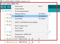
Once you upload the code in the Arduino UNO board, In Arduino IDE, go to “Tools” and click on “Serial Monitor” or use the shortcut “Ctrl+Shift+M.”
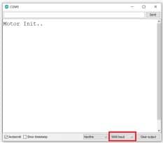
First, ensure that you have selected the correct baud rate, i.e., 9600. Now, in Serial Monitor, you can test your code with DC motors that you have interfaced with Arduino IDE by sending Commands from Serial Monitor.
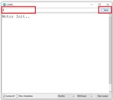
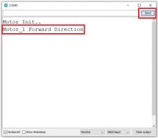
Example 1: Run Motor_1 in the forward direction and then decelerate, accelerate, increase, reduce the speed, reverse the direction and finally stop the motor.
Send following characters one by one in the lower case from Serial Monitor:
f, s, d, a, i, i, i, i, i, i, i, i, i, i, i, i, r, r, r, r, r, r, r, r, r, r, r, r, b, s, h
Similarly, you can also control Motor_2 by sending the above characters in the Upper case. Note that you can run both motors by sending characters as per your requirements.
Example 2: Run Motor_1 & Motor_2 simultaneously in forward, then backward, and stop both motors.
Send following characters:
X, Y, Z
Conclusion
After this tutorial, you can apply the logic used to control the speed and direction of DC Motors to build innovative and creative electronics projects with DC Motors and Arduino Board.
I hope you found this tutorial helpful and informative. If you did, please share it with a friend who also likes electronics and making things!
I would love to know what project you plan on building or have already made with DC motors and the Arduino.
If you have any questions suggestions, or if you think that things are missing in this tutorial, please leave a comment below.

Hiren is a professional Embedded Engineer with a Master’s Degree
in Electronics and Communication Engineering. He is proficient in C and
C++ and enjoys building DIY projects on Arduino, ESP32, PIC32, STM32 & Raspberry PI boards.
Henry Couper
Friday 23rd of September 2022
I want to program the dc motor to accelerate to a selected speed and hold that speed The next step is to use a reed switch to activate the program to de accelerate the motor to stop for ten seconds the continue until the next reed switch. I want the hardware to be as small as possible Thanks