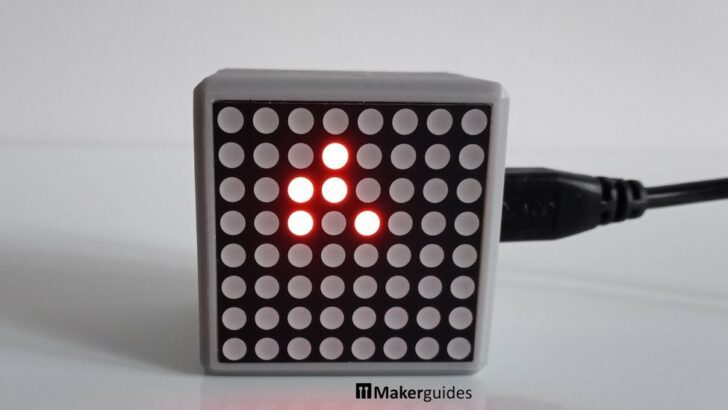
In this tutorial you will learn how to implement the Game of Life on an 8×8 LED Dot Matrix Display using the MAX7219 driver and an Arduino. I will also provide instructions and an implementation for a ESP8266 ESP-12F Mini instead of the Arduino. This will allow you to build an iconic Game of Life in a Cube that runs the glider pattern, shown above.
I doesn’t get much nerdier than that!
What is the Game of Life
The Game of Life, also known as Conway’s Game of Life, is a cellular automaton devised by mathematician John Horton Conway in 1970. It is not a traditional game in the sense of having players or winning or losing conditions. Instead, it is a simulation that follows a set of simple rules and demonstrates complex patterns and behaviors.
The Game of Life takes place on a grid of cells, where each cell can be either alive or dead. The grid can be of any size, but for this tutorial, we will be using an 8×8 LED Dot Matrix Display. The game progresses in discrete time steps, where the state of each cell in the grid is updated based on its current state and the states of its neighboring cells.
Rules
The rules of the Game of Life are as follows:
- A live cell with fewer than two live neighbors dies.
- A live cell with two or three live neighbors lives on.
- A live cell with more than three live neighbors dies.
- A dead cell with exactly three live neighbors becomes alive.
Below you can see five patterns (a,… ,e) and their progression in life over three iterations (0,… ,2). This image is from Martin Gardner’s column in Scientific America, where Conway’s Game of Life was popularized first.
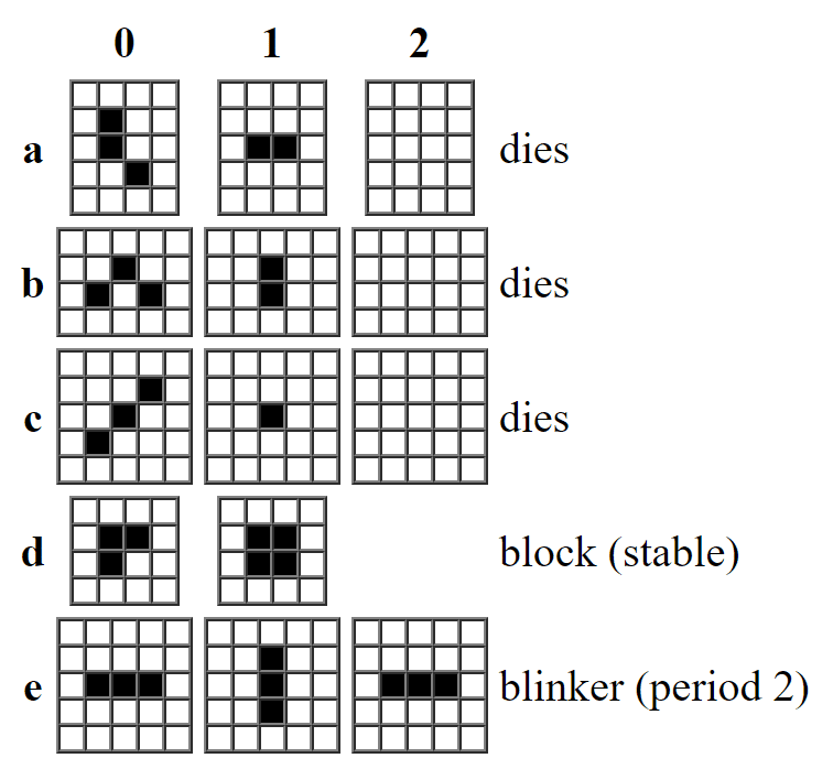
These rules are applied simultaneously to all cells in the grid, which leads to fascinating patterns and behaviors emerging over time. The Game of Life is a classic example of a cellular automaton and has been studied extensively for its mathematical properties and its ability to simulate complex systems.
Glider
The most popular pattern in the Game of Life is the “glider.” A glider is a configuration of cells that moves diagonally across the grid as the game progresses. It is a self-replicating pattern that can be used to create other interesting patterns and structures. Here is an example of a glider in motion:
This is just one of the many interesting and complex patterns that can be created in Conway’s Game of Life. To explore some of these patterns, have a look at this Game of Life simulator, which is tremendous fun to play with. The game has fascinated people for decades and has led to significant research in the fields of mathematics, computer science, and theoretical biology.
Game of Life in a Cube
By implementing it on an 8×8 LED Dot Matrix Display using the MAX7219 driver, you can visualize the game in a tangible way. Below you can see how the Game of Life in a Cube we are going to build will look like when finished.
In the next sections of this tutorial, we will explore the required components, how to connect the display, and the code needed to implement the Game of Life.
Required Components
Below you will find the required part for this project. If you just want to quickly try it out and run the Game of Life go with the Arduino, then instead of buying the suggested 8×8 Dot Matrix Display, buy this one . It is a bigger module and will not fit the the cube but has the advantage that you do not need any soldering.
If you want to build the cube, you will need the ESP8266 ESP-12F Mini (or a similar sized board) and the suggested 8×8 Dot Matrix Display. Note, however, that you need to be able to do some simple soldering of wires and pins.

Arduino Uno
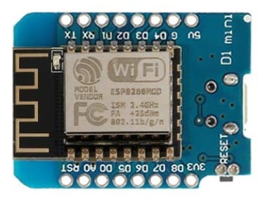
ESP8266 ESP-12F Mini

USB Cable for Arduino UNO

Dupont Wire Set
MAX7219 8×8 Dot Matrix LED Display
Makerguides.com is a participant in the Amazon Services LLC Associates Program, an affiliate advertising program designed to provide a means for sites to earn advertising fees by advertising and linking to products on Amazon.com. As an Amazon Associate we earn from qualifying purchases.
Soldering the Dot Matrix Display
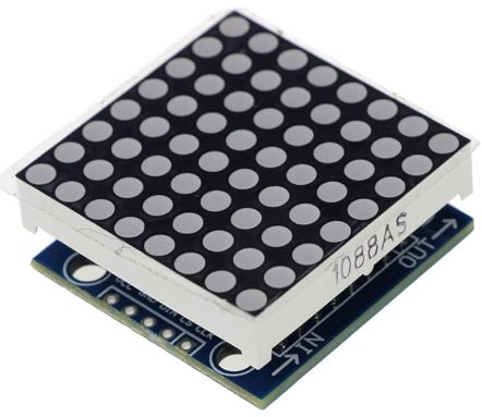
If you buy the listed MAX7219 8×8 Dot Matrix LED Display you will notice that the actual 8×8 LED Display and the board with the MAX7219 driver come separately. You will need to solder them and make sure the orientation is correct. If the part number of the LED Display is at the front, you have to orient the board so that the label “DISY1” on the board is also at the front. See the picture below.
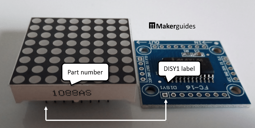
If you use the pin headers, this is not critical, since you can rotate the display later. But if you solder the display directly to the board, you’ll need to get this right.
By the way, the MAX7219 is that black chip on the board. It simplifies controlling the 8×8 Matrix Display significantly and especially reduces the number of GPIO pins we need from the Arduino. For more details have a look at our MAX7219 LED dot matrix display Arduino tutorial and maybe the datasheet itself.
In the next section, I will show you how to connect the display to an Arduino.
Connecting the Dot Matrix Display
Once you have the display soldered to the board, connecting it to an Arduino is simple. The picture below shows the wiring.
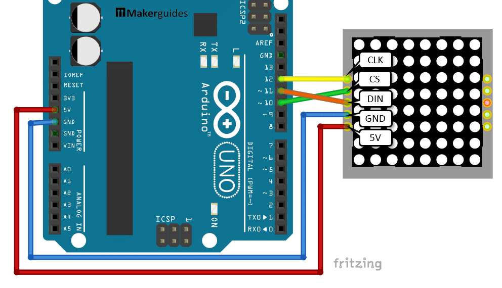
That completes the connection of the display to the Arduino. If you need more details regarding the wiring of the components, here is the complete wiring table.
| From | Pin | Wire color | To | Pin |
| Arduino | 5V | Red | Display | VCC / 5V |
| Arduino | GND | Blue | Display | GND |
| Arduino | 12 | Yellow | Display | CLK |
| Arduino | 11 | Orange | Display | DIN |
| Arduino | 10 | Green | Display | CS |
Code for Game of Life
In this section we will write the code that runs the Game of Life on an Arduino and shows the glider pattern on the Dot Matrix Display.
Install LedControl libary
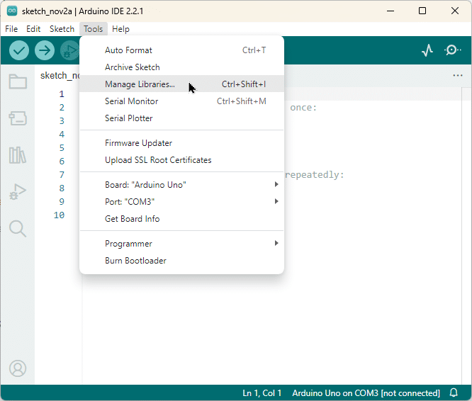
To control the Display we are going to use the LedControl library. The installation is simple. Just go to “Tools” and then “Manage Libraries..” in the Arduino IDE:
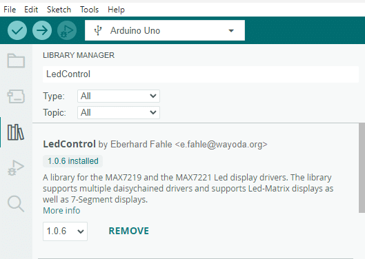
Then search for “LedControl” and install the “LedControl library by Eberhard Fahle“. The picture below shows how that looks like once you have completed the installation. Should take only a second.
Now we are ready to write the Arduino code.
Arduino code
Have a quick look at complete code first to get an overview. I will explain the details in the following sections.
// Game of Life on an 8x8 Dot Matrix Display
#include "LedControl.h"

// Arduino
const byte CLK = 12;
const byte DIN = 11;
const byte CS = 10;

LedControl lc = LedControl(DIN, CLK, CS, 0);

// glider
byte board[8] = {
  B00000000,
  B00000000,
  B00010000,
  B00001000,
  B00111000,
  B00000000,
  B00000000,
  B00000000,
};

void set_bit(byte *b, byte pos, byte val) {
  if (val > 0) {
    *b |= (1 << pos);
  } else {
    *b &= ~(1 << pos);
  }
}

byte get_bit(byte *b, byte pos) {
  return (*b >> pos) & 0x01;
}

void set(byte *board, byte r, byte c, byte val) {
  set_bit(&board[r], c, val);
}

byte get(byte *board, byte r, byte c) {
  return get_bit(&board[r], c);
}

void update_display() {
  lc.clearDisplay(0);
  for (int i = 0; i < 8; i++) {
    lc.setRow(0, i, board[i]);
  }
}

int count_neighbors(byte r, byte c) {
  int count = 0;
  for (int rd = -1; rd <= 1; rd++) {
    for (int cd = -1; cd <= 1; cd++) {
      if (rd == 0 && cd == 0) continue;
      int nr = (r + rd + 8) % 8;
      int nc = (c + cd + 8) % 8;
      count += get(board, nr, nc);
    }
  }
  return count;
}

void update_board() {
  byte temp[8];
  byte alive;
  for (byte r = 0; r < 8; r++) {
    for (byte c = 0; c < 8; c++) {
      int neighbors = count_neighbors(r, c);
      if (get(board, r, c)) {
        alive = !(neighbors < 2 || neighbors > 3);
      } else {
        alive = neighbors == 3;
      }
      set(temp, r, c, alive);
    }
  }
  memcpy(board, temp, sizeof(board));
}

void setup() {
  Serial.begin(9600);
  lc.shutdown(0, false);
  lc.clearDisplay(0);
}

void loop() {
  for (int step = 0; step < 4; step++) {
    lc.setIntensity(0, step);
    update_display();
    update_board();
    delay(500);
  }
}
Constants and Variables
We start by including the necessary LedControl library and defining the pins for the MAX7219 driver. The CLK pin is connected to pin 12, DIN pin is connected to pin 11, and CS pin is connected to pin 10. We also create an instance of the LedControl class with the specified pins.
#include "LedControl.h"

const byte CLK = 12;
const byte DIN = 11;
const byte CS = 10;

LedControl lc = LedControl(DIN, CLK, CS, 0);
Next, we define the initial state of the game board. The board is represented as an 8×8 grid of cells, where each cell can be either alive (1) or dead (0). The initial state is defined using binary notation and each row is one byte with 8 bits. Since we have 8 rows we get an 8×8 bit matrix that matches the dimension of our 8×8 LED Dot Matrix Display.
byte board[8] = {
  B00000000,
  B00000000,
  B00010000,
  B00001000,
  B00111000,
  B00000000,
  B00000000,
  B00000000,
};
Helper Functions
We define two helper functions, set_bit() and get_bit(), to manipulate individual bits in a byte. These functions are used to set or get the value of a specific bit in the game board.
void set_bit(byte *b, byte pos, byte val) {
  if (val > 0) {
    *b |= (1 << pos);
  } else {
    *b &= ~(1 << pos);
  }
}

byte get_bit(byte *b, byte pos) {
  return (*b >> pos) & 0x01;
}
We also define two functions, set() and get(), to set or get the value of a specific cell in the game board. These functions use the set_bit() and get_bit() functions to manipulate the individual bits in the game board.
void set(byte *board, byte r, byte c, byte val) {
  set_bit(&board[r], c, val);
}

byte get(byte *board, byte r, byte c) {
  return get_bit(&board[r], c);
}
Display and Update Functions
The update_display() function is responsible for updating the LED dot matrix display with the current state of the game board. It clears the display and then sets the rows of the display based on the values in the game board. Note that we set entire rows at once, since it is simpler and faster than setting the individual bits.
void update_display() {
  lc.clearDisplay(0);
  for (int i = 0; i < 8; i++) {
    lc.setRow(0, i, board[i]);
  }
}
The count_neighbors() function counts the number of alive neighbors for a given cell in the game board. It iterates over the neighboring cells and checks their values using the get() function.
int count_neighbors(byte r, byte c) {
  int count = 0;
  for (int rd = -1; rd <= 1; rd++) {
    for (int cd = -1; cd <= 1; cd++) {
      if (rd == 0 && cd == 0) continue;
      int nr = (r + rd + 8) % 8;
      int nc = (c + cd + 8) % 8;
      count += get(board, nr, nc);
    }
  }
  return count;
}
The update_board() function updates the game board based on the rules of the Game of Life. It creates a temporary board temp to store the updated values. For each cell in the game board, it counts the number of alive neighbors using the count_neighbors() function and applies the rules to determine whether the cell should be alive or dead. The updated values are then set in the temporary board using the set() function. Finally, the updated values are copied back to the original game board using the memcpy() function.
void update_board() {
  byte temp[8];
  byte alive;
  for (byte r = 0; r < 8; r++) {
    for (byte c = 0; c < 8; c++) {
      int neighbors = count_neighbors(r, c);
      if (get(board, r, c)) {
        alive = !(neighbors < 2 || neighbors > 3);
      } else {
        alive = neighbors == 3;
      }
      set(temp, r, c, alive);
    }
  }
  memcpy(board, temp, sizeof(board));
}
Setup and Loop Functions
In the setup() function, we initialize the serial communication for debugging purposes, disable the shutdown mode of the MAX7219 driver, and clear the display.
void setup() {
  Serial.begin(9600);
  lc.shutdown(0, false);
  lc.clearDisplay(0);
}
In the loop() function, we run the Game of Life for four steps. This is, because the period for the Glider pattern is 4 steps as well. After 4 iteration the Glider shows the same pattern but has moved diagonally one step further.
For each step, we set the intensity of the LED dot matrix display. This highlights the different phases of the evolution of the Glider pattern. If you want the Glider to be displayed with a constant brightness you can change that here. Intensity value range from 0 to 15.
After that we update the display with the current state of the game board using the update_display() function, update the game board using the update_board() function, and delay for 500 milliseconds before the next step. The delay is just to slow down the Glider. Again that is something you can easily change.
void loop() {
  for (int step = 0; step < 4; step++) {
    lc.setIntensity(0, step);
    update_display();
    update_board();
    delay(500);
  }
}
And that’s it! Now you have the Game of Life running on an Arduino. Of course, this is just the beginning. In addition to the Glider there are many other interesting patterns you could add to the program. Those different patterns could then be selected via a button, a rotary encoder or another input device.
However, having everything in a nice housing and the possibility to control the device via a web interface would be so much cooler. And that is what I will show you in the next section.
We will not implement the web interface but we will be using the ESP8266 ESP-12F Mini that is WiFi enable, so that we can add this functionality later. Furthermore, the ESP8266 ESP-12F Mini is about the same size as the Dot Display, which allows us to pack everything neatly in a Cube.
Let’s go on and put the Game of Life in a Cube!
Setting up the ESP8266 ESP-12F Mini
Communication with the ESP8266 requires that a CH340 driver is installed. We also will need to install the board itself. How that is done, I’ll show you in the sections below.
Installing the CH340g driver
The CH340 driver is the software for a USB-to-serial converter chip that allows the board to communicate with the computer via USB. This driver is commonly used in boards that do not have a built-in USB interface. We will need this to program the ESP8266 over the COM/USB port.
- Download the Windows CH340 Driver
- Unzip the file
- Run the installer which you unzipped
- Connect your ESP8266 with an USB cable and you should see an active COM port in the Arduino IDE
Installing the ESP8266 board
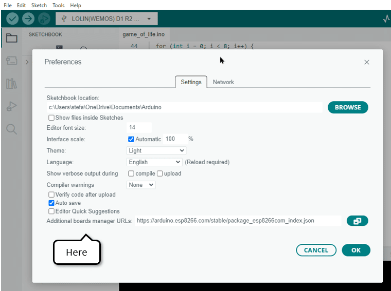
Next we need to install the ESP8266 board. Go to “File” and “Preferences” and enter the following URL into the “Additional Boards Manager” URLs field:
http://arduino.esp8266.com/stable/package_esp8266com_index.json
The picture below shows where you can find the URLs field in the Preferences dialog.
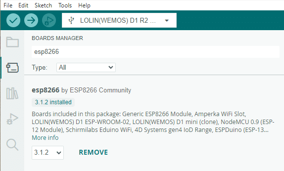
Then open “Tools“, “Board” and “Boards Manager” and install “esp8266 by ESP8266 Community“.
Phew, almost done. We now can communicate with the board and compile and upload sketches. But first we need to change the code a tiny bit, since the ESP8266 will be using different pins than the Arduino to talk to the LED display.
Pin constants and wiring
Simply replace the pin constants in the code that are for the Arduino with the following ones.
// ESP8266 ESP-12F Mini
const byte DIN = 12;  // D6
const byte CS = 14;   // D5
const byte CLK = 13;  // D7
Of, course we now also need to wire up the ESP8266 and the Dot Matrix Display accordingly. Connect D6 to DIN, D5 to CS and D7 to CLK. Finally connect the power (5V to VCC and G to GND). In the picture below you can see how this should look like when you are finished.
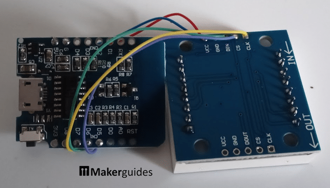
Double check the wiring and the new pin constants and then we can upload the Game of Life sketch to the ESP8266. The wires need to be connected to the input side, marked with “-> IN”, of the display board.
Select ESP8266 board and upload sketch
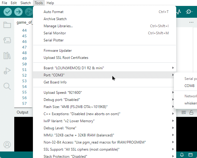
Open the Arduino IDE and under “Tools“, “Board“, “ESP8266” select the “LOLIN(WEMOS) D1 R2 and mini” board.

You should now be able to compile and upload the sketch as usual. And the display should then show the Glider crawling across the game board.
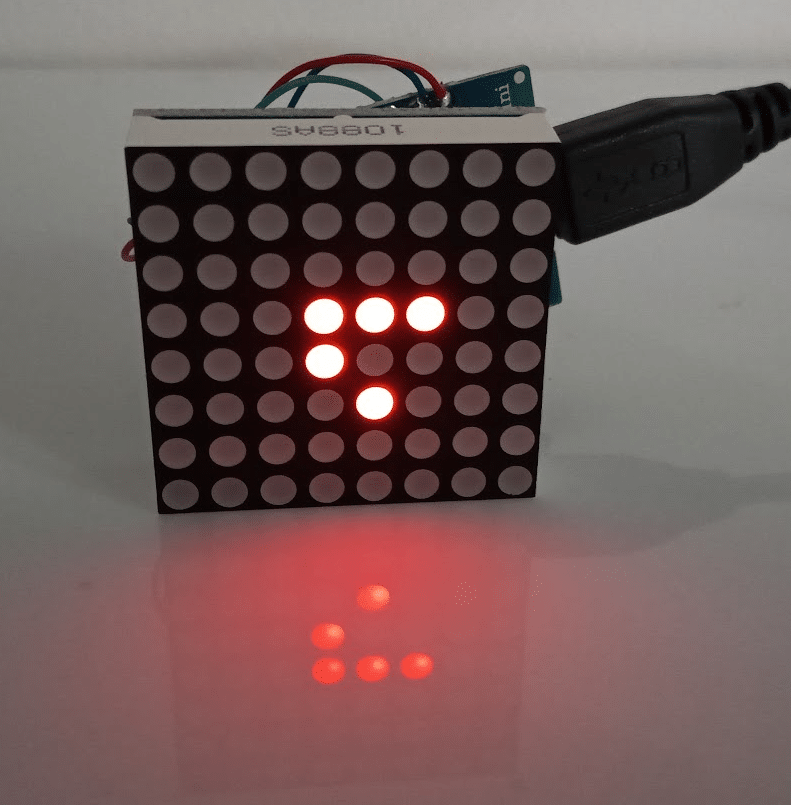
Congratulations! The last step is to build the Cube and put everything in it.
Building an Enclosure
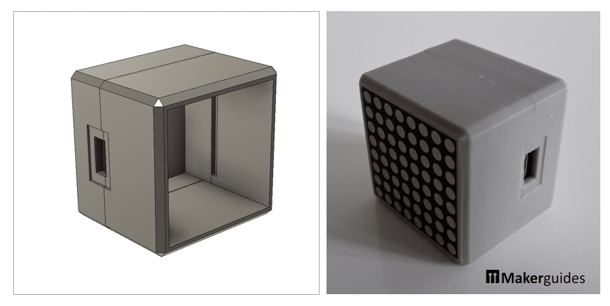
I used a 3D printer and printed the two parts shown below. You can download the STL files for the two parts here.
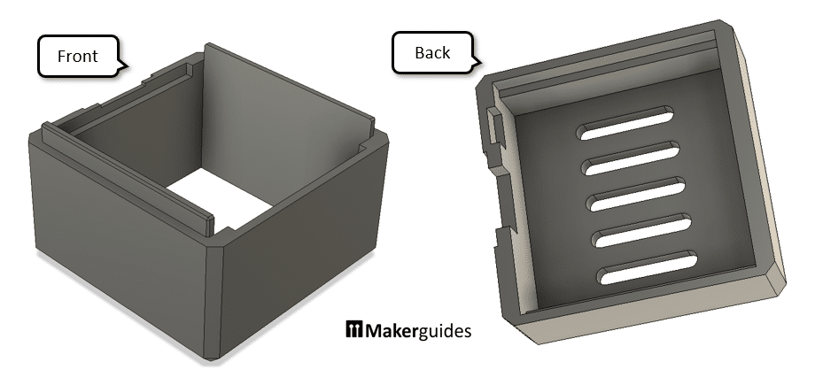
The Dot Matrix Display is just a (tight) press-fit in the front frame and the ESP8266 sits in the middle between the two parts, fixed with some hot glue for additional stability. If you snap the two parts together, you are done. The pictures below show the complete enclosure with and without the display and board.
And that’s it. A great looking Game of Life in a Cube!
As I said before, this is just the beginning! We could add many more patterns in addition to the iconic “Glider”. A similar an interesting pattern is the Lightweight Spaceship. Give it a go:
// lightweight spaceship
byte board[8] = {
   B00000000,
   B00100100,
   B01000000,
   B01000100,
   B01111000,
   B00000000,
   B00000000,
   B00000000,
};
And here another idea: with a Wi-Fi capable board inside the cube could be completely controlled via a web interface, including defining new patterns to run. It is all up to you!
Summary
In this tutorial, we have successfully implemented the Game of Life on an 8×8 LED Dot Matrix Display using the MAX7219 driver. We started by understanding what the Game of Life is and how it works. Then, we listed the required components for this project, which included an Arduino board, an 8×8 LED Dot Matrix Display, and the MAX7219 driver.
Next, we went through the process of connecting the LED Dot Matrix Display to the Arduino board using the MAX7219 driver. We explained the wiring connections and provided a clear diagram to make the process easier for you.
After that, we delved into the code for the Game of Life. We explained the logic behind the implementation and provided a step-by-step guide on how to write the code. We also included the complete code for your reference.
By following the instructions in this tutorial, you should now have a working Game of Life on your LED Dot Matrix Display. You can experiment with different initial configurations and observe how the patterns evolve over time.
If you have any further questions or interesting ideas feel free to leave a comment.
Links
Here some additional link that you may find interesting or helpful.
- MAX7219 LED dot matrix display Arduino tutorial
- Inventing Game of Life (John Conway) – Numberphile
- Game of Life online simulator
- Collection of interesting patterns in Game of Life
- Link Collection for Game of Life
- The fantastic combinations of John Conway’s new solitaire game “life”
Stefan is a professional software developer and researcher. He has worked in robotics, bioinformatics, image/audio processing and education at Siemens, IBM and Google. He specializes in AI and machine learning and has a keen interest in DIY projects involving Arduino and 3D printing.