In this tutorial, you will learn how to build a Spin the Wheel game using LEDs, a buzzer, and an Arduino. The Spin the Wheel game is a fun and interactive game that can be used for various purposes, such as deciding who goes first in a game, selecting a random winner for a prize, or simply for entertainment.
Traditionally it features a large mechanical wheel segmented into colored slices. Each slice is marked with a number or a prize, and the segments may have different sizes, indicating the odds of landing on them. The wheel is mounted vertically so that it can spin freely when a player rotates it, either by hand or by pulling a lever attached to it.
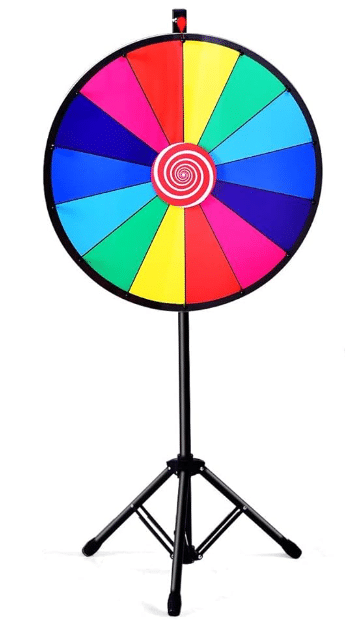
Players typically bet on where the wheel will stop. After placing their bets on a numbered or colored area of a static board that corresponds to the wheel’s segments, the game host or player spins the wheel. When the wheel comes to a stop, a pointer at the top indicates the winning segment.
Here we will build a small, electronic version of the game that uses a ring of LEDs to highlight a winning segment instead of a mechanically spinning wheel. We also add a buzzer for sound effects such as the clicking of the spinning wheel and the signalling of a win.
By following this tutorial, you will learn how to read a push button, control LEDs and a buzzer using an Arduino. You will also learn how to create a spinning effect using LEDs to simulate the motion of a wheel.
So, let’s get started and create your own Spin the Wheel game using Arduino!
Required Parts
Below you will find the parts required for this project. If you already have a resistor set and eight LEDs you will not need the suggested kit. You can build the project on a breadboard first but you won’t need that if you want to build an actual wheel and wire up the LEDs directly. For that the Wire Set with Clips will come in handy.

Arduino Uno

Dupont Wire Set
Wire Set with Clips

Breadboard
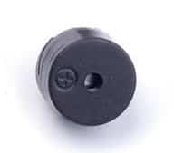
Passive Buzzer
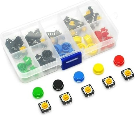
Push Button Set

Resistor & LED kit
Makerguides.com is a participant in the Amazon Services LLC Associates Program, an affiliate advertising program designed to provide a means for sites to earn advertising fees by advertising and linking to products on Amazon.com. As an Amazon Associate we earn from qualifying purchases.
Spin the Wheel
In this section, I’ll show you how to connect the parts and how to write the code for the Spin the Wheel game. To keep the wiring and the code simple, I will use only four LEDs, while the actual wheel shown above has eight. But the wiring and code is easy to extend to more LEDs.
Wiring
The following picture shows the wiring of the Spin the Wheel game for four LEDs. Just use the remaining pins (6,7,8,9) to extend to eight LEDs, if you want to.
Let’s start by connecting the LEDs. Since only one LED will be lit at a time, we need only one current limiting resistor of 220 Ohm between the GND pin of the Arduino and all the cathode pins (short pins) of the four LEDs. You can switch on more than one LED (without damaging your Arduino) but the LEDs will be dimmer.
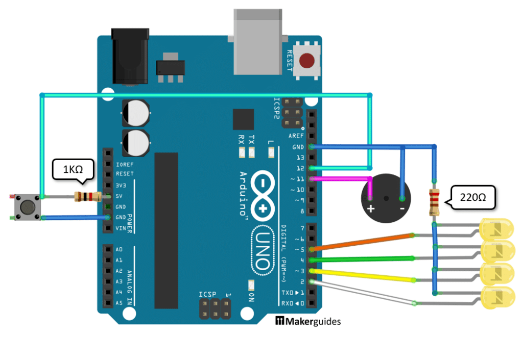
Next, connect the longer pins for LEDs to the GPIO outputs 2,3,4 and 5 of the Arduino. As I mentioned, for eight LEDs connect the pins 6,7,8,9 in the same manner.
Then, we connect the buzzer. Note that it is a passive buzzer with polarity. The negative pin must be connected to ground (GND) and the positive pin we connect to GPIO 11. Otherwise, you will not hear any sound.
Lastly the push button that activates the game. We need a pull-up resistor of 1 Kilo Ohm that is connected to 5V and to the button. The same button pin is also connected to GPIO 12. And finally the other button pin needs to be connected to ground.
And that completes the wiring. If you are unsure have a look at the detailed wiring table below.
Wiring table
| From | Pin | Wire color | To | Pin |
| Arduino | GND | Blue | Resistor 220Ω | 1 |
| Resistor 220Ω | 2 | Blue | LED1 | Cathode |
| Resistor 220Ω | 2 | Blue | LED2 | Cathode |
| Resistor 220Ω | 2 | Blue | LED3 | Cathode |
| Resistor 220Ω | 2 | Blue | LED4 | Cathode |
| Arduino | 2 | White | LED1 | Anode |
| Arduino | 3 | Yellow | LED2 | Anode |
| Arduino | 4 | Green | LED3 | Anode |
| Arduino | 5 | Orange | LED4 | Anode |
| Arduino | GND | Blue | Buzzer | Negative Pin |
| Arduino | 11 | Purple | Buzzer | Positive Pin |
| Arduino | 5V | – | Resistor 1KΩ | 1 |
| Resistor 1KΩ | 1 | – | Button | 1 |
| Button | 1 | Cyan | Arduino | 12 |
| Button | 2 | Blue | Arduino | GND |
Code
In this section we will implement the code that controls the game. We want the LEDs to light up in a circular sequence that slows down over time until it stops completely. At the same time we want to make a clicking sound, similar to the sound the spinning wheel makes and play a winning sound, when the wheel stops. Finally, we want to start the game when the button is pressed.
The code below does all of that. Have a quick look to get an overview. After that we go into its details.
const int btnPin = 12;
const int buzzerPin = 11;
const int nLeds = 4;
const byte ledPins[] = { 2, 3, 4, 5 };

int curLed = 0;

void setLed(int state, int pause) {
  digitalWrite(ledPins[curLed], state);
  delay(pause);
}

void spin(int pause) {
  curLed = (curLed + 1) % nLeds;
  tone(buzzerPin, 100, 5);
  setLed(HIGH, pause);
  setLed(LOW, 0);
}

void win() {
  for (int i = 0; i < 10; i++) {
    tone(buzzerPin, 1000, 100);
    setLed(LOW, 100);
    tone(buzzerPin, 1500, 100);
    setLed(HIGH, 100);
  }
  noTone(buzzerPin);
}

void setup() {
  pinMode(buzzerPin, OUTPUT);
  for (int i = 0; i < nLeds; i++) {
    pinMode(ledPins[i], OUTPUT);
  }
}

void loop() {
  int button = digitalRead(btnPin);
  if (button == LOW) {
    setLed(LOW, 0);
    int start = random(1, 50);
    for (int pause = start; pause < 300; pause += 10) {
      spin(pause);
    }
    win();
  }
  delay(100);
}
Constants and Variables
We start by defining the constants and variables used in the code. The btnPin constant specifies the pin to which the button is connected. The buzzerPin constant specifies the pin to which the buzzer is connected.
The nLeds variable specifies the number of LEDs used in the game. The ledPins array contains the pins to which the LEDs are connected. If you want to add more LEDs simply extend the ledPins array and adjust the nLEDs constant accordingly.
const int btnPin = 12;
const int buzzerPin = 11;
const int nLeds = 4;
const byte ledPins[] = { 2, 3, 4, 5 };
The curLed variable controls which LED is currently active. It is an index into the ledPins array. All other LEDs will be inactive.
int curLed = 0;
setLed function
The setLed() function is responsible for setting the state of the current LED and pausing for a specified duration. It takes two parameters: state (HIGH or LOW) and pause (the duration in milliseconds to pause after setting the LED state).
If you have difficulties with this have a look at our tutorial on How To Blink An LED Using Arduino.
void setLed(int state, int pause) {
  digitalWrite(ledPins[curLed], state);
  delay(pause);
}
spin function
The spin() function is called when the button is pressed to start the wheel spinning. It increments the curLed variable to select the next LED in the sequence. It also plays a very short (5ms), low (100Hz) tone on the buzzer. This will sound like the indicator hits the pins of spinning wheel. Then, it calls the setLed() function to turn on the current LED for a specified pause duration and then turn it off.
The expression curLed = (curLed + 1) % nLeds ensures that curLed loops around and resets to 0, when it becomes equal to the number of LEDs (nLeds).
If you want to learn more about controlling a buzzer you can read How To Interface A Piezo Buzzer With Arduino.
void spin(int pause) {
  curLed = (curLed + 1) % nLeds;
  tone(buzzerPin, 100, 5);
  setLed(HIGH, pause);
  setLed(LOW, 0);
}
win function
The win() function is called when the wheel stops spinning. It plays a sequence of tones on the buzzer and alternates turning on and off the LEDs for a visually appealing effect. After the melody is played, the buzzer is turned off.
void win() {
  for (int i = 0; i < 10; i++) {
    tone(buzzerPin, 1000, 100);
    setLed(LOW, 100);
    tone(buzzerPin, 1500, 100);
    setLed(HIGH, 100);
  }
  noTone(buzzerPin);
}
Setup function
In the setup() function, we set the pinMode for the buzzer pin to OUTPUT, as we will be writing to it. We also set the pinMode for each LED pin in the ledPins array to OUTPUT. And the btnPin is set to INPUT, since we are going to read the button state.
void setup() {
  pinMode(btnPin, INPUT);
  pinMode(buzzerPin, OUTPUT);
  for (int i = 0; i < nLeds; i++) {
    pinMode(ledPins[i], OUTPUT);
  }
}
Loop function
The loop() function is the main part of the code that runs continuously. It first reads the state of the button using digitalRead(). If the button is pressed (LOW), it turns off the current LED, generates a random start value for the pause duration, and then calls the spin() function repeatedly with increasing pause durations until a maximum value is reached (500ms). Finally, it calls the win() function to play the winning sequence.
For more information on how to read a button have a look at our tutorial on How To Use A Push Button With Arduino.
void loop() {
  int button = digitalRead(btnPin);
  if (button == LOW) {
    setLed(LOW, 0);
    int start = random(1, 50);
    for (int pause = start; pause < 500; pause += 10) {
      spin(pause);
    }
    win();
  }
  delay(100);
}
And that’s it! With this code you get a nice spinning wheel effect. Once the button is pressed the LED’s light up in circular order and since the pause time is steadily increasing, the sequence gets slower and slower until the winning state is reached. After that you can press the button again. And since the start is random the spinning time varies for each button press.
3D Printed Wheel
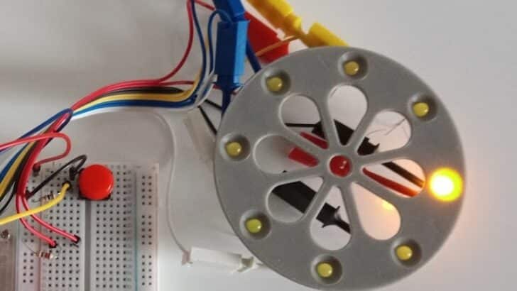
You can easily place four LEDs on a breadboard but with eight LEDs it gets difficult. I wanted to have a nice wheel and used my 3D printer to print an LED holder in the shape:
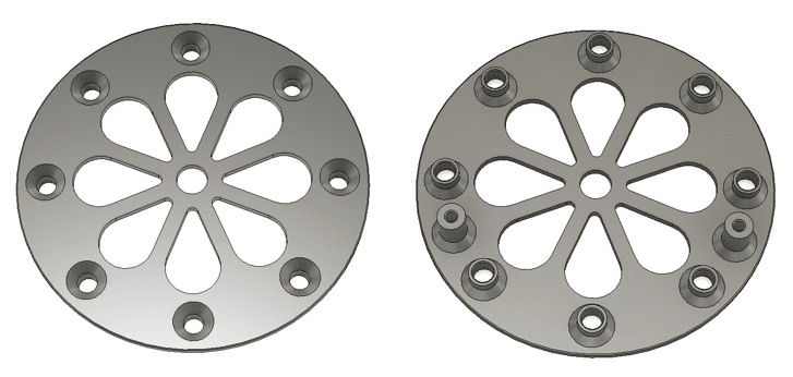
You can download the STL file for the Wheel here. Note the two holders for at the back, where you can insert two wooden skewer. This allows you to position the wheel in an angle, if you want to. The picture below shows how the actual 3d-printed wheel looks like when the LEDs are placed.
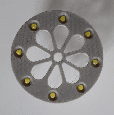
Feel free to use this as a starting point for a nicer design. I would like to print a complete housing with an integrated Arduino Nano and the start button in the center. But that is for another tutorial.
Conclusion
In this tutorial, we have learned how to build a Spin the Wheel game. By following the step-by-step instructions, you should now have a fully functional game.
We started by gathering all the required parts, which include an Arduino board, LEDs, a button, a buzzer, and a push button. Next, we went through the process of wiring the components to the Arduino board. It is important to pay attention to the connections otherwise the LEDs will not light up in the correct order. Once the wiring was complete, we moved on to the coding part.
In conclusion, building a Spin the Wheel game is a fun and engaging project that showcases the versatility of Arduino boards. It allows you to combine hardware and software to create an interactive game that can be enjoyed by people of all ages.
So why not gather the required parts, follow the instructions provided in this tutorial, and create your own Spin the Wheel game? It’s a great way to learn more about Arduino, enhance your coding skills, and have fun with your friends and family.
If you have any questions or face any difficulties during the process, feel free to refer to the Frequently Asked Questions section or reach out to the Arduino community for support. Happy building!
Frequently Asked Questions
Here are some frequently asked questions about building a Spin the Wheel game.
What is a Spin the Wheel game?
A Spin the Wheel game is a popular game where players spin a wheel to determine their prize or outcome. It is often used in game shows, carnivals, and events to add an element of excitement and chance.
How does the Spin the Wheel game work?
The Spin the Wheel game works by using the Arduino to control the LEDs and buzzer based on the input from the push-button or switch. When the button is pressed, the Arduino lights up the LEDs in a sequence while playing a sound effect through the buzzer. The sequences slows down until a final LED is lit, signalling the end of the game.
Can I customize the outcomes of the Spin the Wheel game?
Yes, you can customize the outcomes of the Spin the Wheel game according to your preferences. You can assign different prizes, actions, or messages to each LED and modify the Arduino code accordingly.
Are there any additional features I can add to the Spin the Wheel game?
Absolutely! You can enhance the Spin the Wheel game by adding additional features such as a display to show the selected outcome, a motor to physically spin the wheel, or even wireless connectivity to control the game remotely.
Can I have more than eight LEDs on the Wheel?
The number of GPIO ports on an Arduino Uno is limited. If you want to add more LEDs, let’s say 16, you will either need a bigger board with more GPIO pins or use a GPIO expander. See our tutorial Using GPIO Expander MCP23017 With Arduino, which would allow you to control up 128 LEDs!
Can I light up more than one LED at a time?
Yes, you can. But since all LEDs are connected through a single current limiting resistor the more LEDs are active the dimmer they get. You can connect them individually to avoid this but then you may need an additional power supply.
If you have any further questions or need assistance, feel free to leave a comment on the blog post, and our team or the community will be happy to help you out.
Stefan is a professional software developer and researcher. He has worked in robotics, bioinformatics, image/audio processing and education at Siemens, IBM and Google. He specializes in AI and machine learning and has a keen interest in DIY projects involving Arduino and 3D printing.