In this tutorial you will learn how to find the default pins for the I2C and SPI interface for the microcontrollers supported by the Arduino IDE, such as Arduino, ESP32 and ESP8266
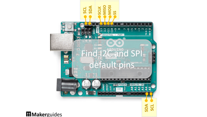
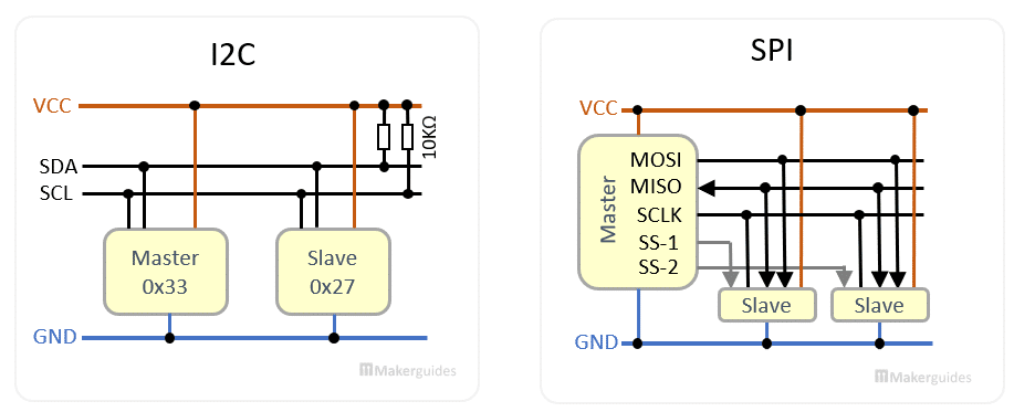
Many external hardware devices such as displays or sensors use the I2C or SPI protocol to communicate with your microcontroller. I2C is a two-wire protocol that uses the SDA and SCL signals and SPI is a four-wire protocol with SS, MSOI, MISO, SCK.
To connect an I2C or and SPI device to your microcontroller you need to know which pins on your microcontroller are the I2C (SDA,SCL) or SPI (SS, MSOI, MISO, SCK) pins.
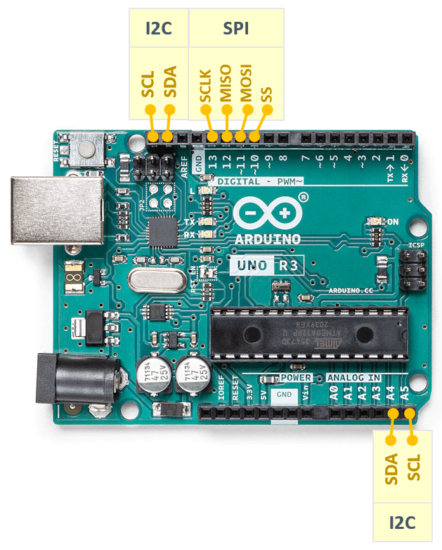
For the more common development boards such as most of the Arduino boards, those pins are usually well documented and easy to find out or labelled on the board. However for some more exotic, older or cloned boards, especially from the ESP8266 and ESP32 family documentation is often lacking.
Print I2C and SPI default pins
As long as you can see your board (or a compatible board) in the Board Manager there is a simple way to print out the default pins for the I2C and SPI interface. The screenshot below shows how to select the Arduino Uno in the board manager, and also which other Arduino boards are available:
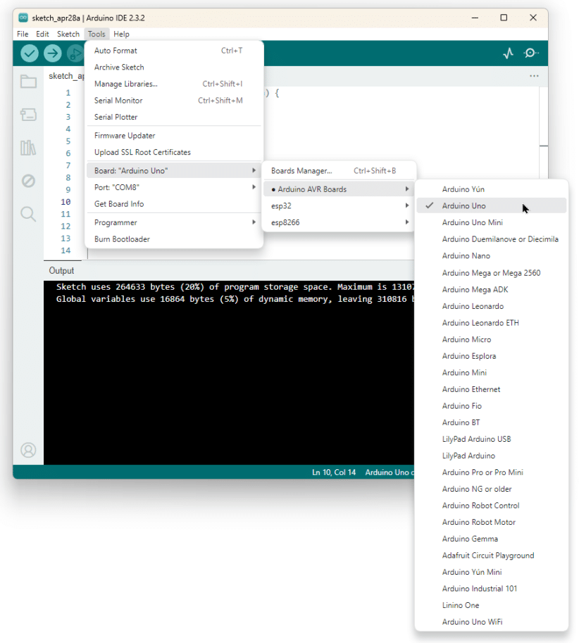
Once you have selected your board you can run the following code. It utilizes the constants for those pins that are defined for all/most development boards to print them to the Serial Monitor.
void print(const char* name, int pin) {
  Serial.print(name);
  Serial.println(pin);
}

void setup() {
  Serial.begin(9600);
}

void loop() {
  print("LED:  ", LED_BUILTIN);

  print("SDA:  ", SDA);
  print("SCL:  ", SCL);

  print("SS:   ", SS);
  print("MOSI: ", MOSI);
  print("MISO: ", MISO);
  print("SCK:  ", SCK);

  delay(5000);
}
Just make sure to set the correct baud rate for your Serial Monitor. It may change depending on the board you select. Other baud rates than 9600 are fine but the baud rate in the code (Serial.begin()) and in the Serial Monitor must match, otherwise you will see gibberish.
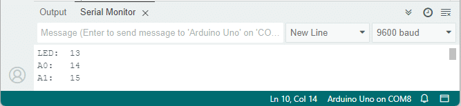
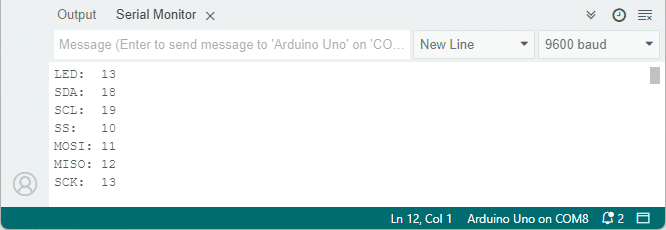
If you upload and run the code above for an Arduino Uno you should see the following output on the Serial Monitor:
You can find the pin definitions in the pins_arduino.h file for standard Arduinos. For variants such as Mega, Leonardo, and others look in the subfolder variants.
I2C and SPI for ESP32 and ESP8266
The above code works the same for most ESP32 or ESP8266 boards but you must have installed the ESP32 or ESP8266 core first. Have a look at our tutorial on How to Program ESP32 with Arduino ID, if you have trouble with installing the ESP32 core.
Installing the ESP8266 core works the same. But if you need help have a look at the Game of Life on a Dot Matrix Display with MAX7219 tutorial, where I explain in detail how to install the ESP8266 core as well.
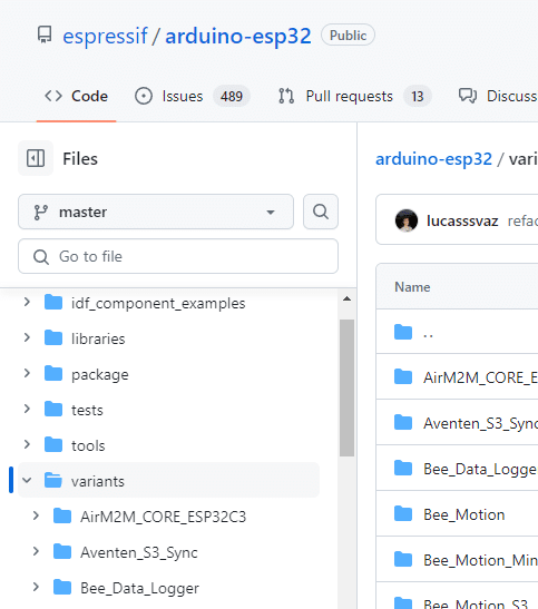
For each board type there will be different pin definitions in the file pins_arduino.h. The different board types are organized in a subfolder called “variants“. See ESP32 board variants and the ESP8266 board variants. The screenshot below shows the folder structure with the variants folder for the ESP32 boards:
Each of the board specific sub-folders will have a pins_arduino.h file. For instance, here is the pins_arduino.h for the standard ESP32 and here is the pins_arduino.h for the WEMOS LOLIN32 lite – a board that I frequently use.
Note that these are the default pin definitions and for most ESP32 and ESP8266 boards you can change, which pins you want to use for I2C and SPI. Also depending on the board, some definitions may be missing and some will have additional definitions, e.g. A0, A1, … for analog inputs or TX and RX for the serial interface.
Conclusions
I hope this little piece of code is useful and if you have any questions feel free ask.
Have fun ; )
Stefan is a professional software developer and researcher. He has worked in robotics, bioinformatics, image/audio processing and education at Siemens, IBM and Google. He specializes in AI and machine learning and has a keen interest in DIY projects involving Arduino and 3D printing.