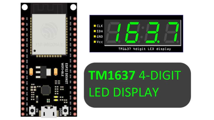
In this guide I will show you how to use the TM1637 7-segment LED driver with an ESP32 microcontroller.
Where do you find a 4-digit 7-segment display used?
Almost everywhere! Weighing scales, billing counters in the shops, treadmills in the gym, elevators, waiting rooms in hospitals, shops, and more!
In this article, I will show you how to display numbers and messages using TM1637.
I provide a connection guide and example code that you can understand and use to test your ESP32 and TM1637 projects.
By the end of this article, you will have a good understanding of how the TM1637 works, the options to optimize your design, and some tips to make your project more successful!
Let’s get started!
Components Needed To Build ESP32 And TM1637 Display Project
Hardware Components
- Dupont wire x 1 set
- Micro USB Cable for ESP32 (for powering ESP32 and programming) x 1
Software
Guide
Makerguides.com is a participant in the Amazon Services LLC Associates Program, an affiliate advertising program designed to provide a means for sites to earn advertising fees by advertising and linking to products on Amazon.com.
Basics of The TM1637 Display Driver
The TM1637 display driver is a useful module for many different applications, which I’ll cover in a minute. But first let’s look at its’ key functional features.
Functional Features of TM1637 IC
- Brightness adjustment circuit (8-duty ratio)
- Built-in RC oscillator
- Built-in blanking circuit
- CMOS technology for optimized power and speed
- Two-wire serial interface (CLK, DIO)
Pin details of TM1637 IC
The TM1637 is a 20-pin IC. The pin details of the TM1637 IC are given in the table below.
| Pin Number | Pin Name |
| 1 | GND |
| 2 | SEG1 / KS1 |
| 3 | SEG2 / KS2 |
| 4 | SEG3 / KS3 |
| 5 | SEG4 / KS4 |
| 6 | SEG5 / KS5 |
| 7 | SEG6 / KS6 |
| 8 | SEG7 / KS7 |
| 9 | SEG8 / KS8 |
| 10 | GRID6 |
| 11 | GRID5 |
| 12 | GRID4 |
| 13 | GRID3 |
| 14 | GRID2 |
| 15 | GRID1 |
| 16 | VDD |
| 17 | DIO |
| 18 | CLK |
| 19 | K1 |
| 20 | K2 |
The pin functions are easy to understand. Here is the pin description.
- DIO → DIO is a data pin. It is bidirectional. You use this pin to send data to the LCD module.
- CLK → The serial data is sent synchronously using this clock pin
- K1 – K2 → Keyboard scan pins. Used to scan keys
- SG1 – SG8 → These are open drain Segment output pins. Connect these pins to the SEG pins of the 7-segment display
- GRID6 – GRID1 → These are bit output pins and are open drain
- VDD, GND → Power and ground connections
How to do TM1637 and ESP32 communication work?
The ESP32 communicates with the TM1637 IC via a 2 wire interface. It is not the same as the I2C protocol as there is no slave address concept here.
The Data on the DIO pin must not change when the clock pin is high. The data can change when the clock pin is low. It is helpful when you are trying to build the library from scratch.
The TM1637 chip acknowledges the data every time with an ACK signal (please refer to the image below).
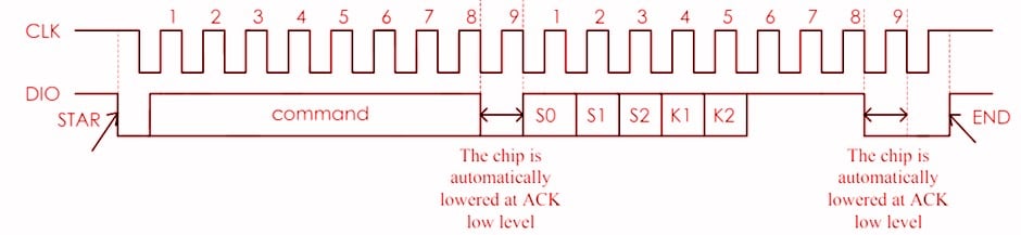
Notice how the data changes only when the clock is low. Also, notice the AC signal asserted by the TM1637 IC at the end of the communication.
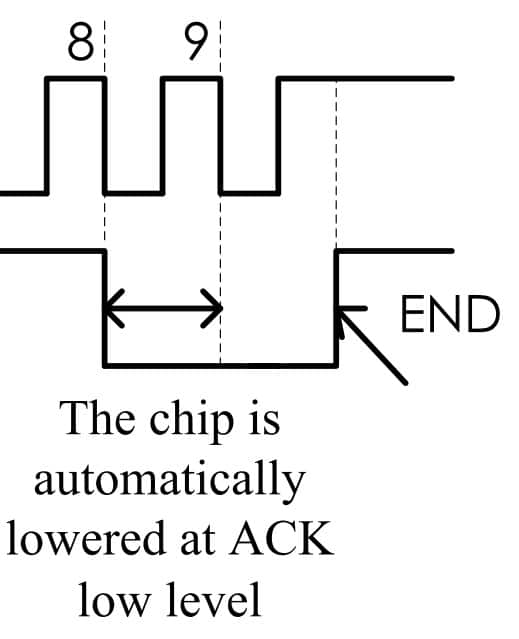
ACK signal helps ESP32 to confirm the communication.
Commands
Commands are used to set the display mode and the LED driver status.
The bits B7 and B6 will tell what type of command it is.
| B7 | B6 | Command |
| 0 | 0 | Data command setting |
| 1 | 0 | Display and control command setting |
| 1 | 1 | Address command setting |
So there are three command types. Let’s see what each command does
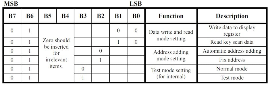
Data Command
This command is used to read and write data, as shown in this table:
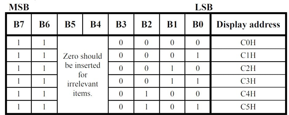
Address Command
This command is used to set the display register address. If the address is C6H or higher, it will be ignored. By default, after powering on the address will be C0H.
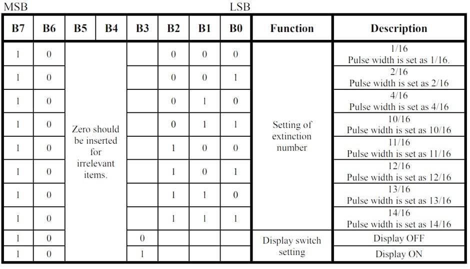
Display Control
This command is used to turn on or turn off the display. You can also use it to set the brightness levels ( 8 levels are supported).
No design is complete without looking at the electrical parameters. It helps you to make sure you are choosing the right power supply and right voltage levels to power the circuit.
Electrical Parameters
| Parameters | Minimum | Typical | Maximum |
| Logic power supply voltage (VDD) | – | 5 V | – |
| High-level input voltage2 | 0.7 X VDD | – | VDD |
| Low-Level input voltage | 0 V | – | 0.3 X VDD |
| LED sink current | – | – | 50 mA |
| Operating temperature | – 40 ℃ | 25 ℃ | 85 ℃ |
| Clock frequency | – | – | 500 kHz |
Applications of TM1637 Chip
The display driver chip TM1637 is commonly used to drive 7-segment displays. The applications include
- Digital clocks and timers
- Weather display unit (temperature and humidity)
- Counters and timers
- Scoreboard for games
- Speedometer and fuel gauge display
- Weighing machines etc
The TM1637 is an easy-to-use IC with a simple interface to ESP32 and Arduino boards. Hence it is very popular.
Instructions To Connect The TM1637 Module with ESP32
In this section, we will build a project using ESP32 and the TM1637 display module. Let’s get started with the hardware connections.
Below are the simple connections to interface the model TM1637 to the ESP32 module.
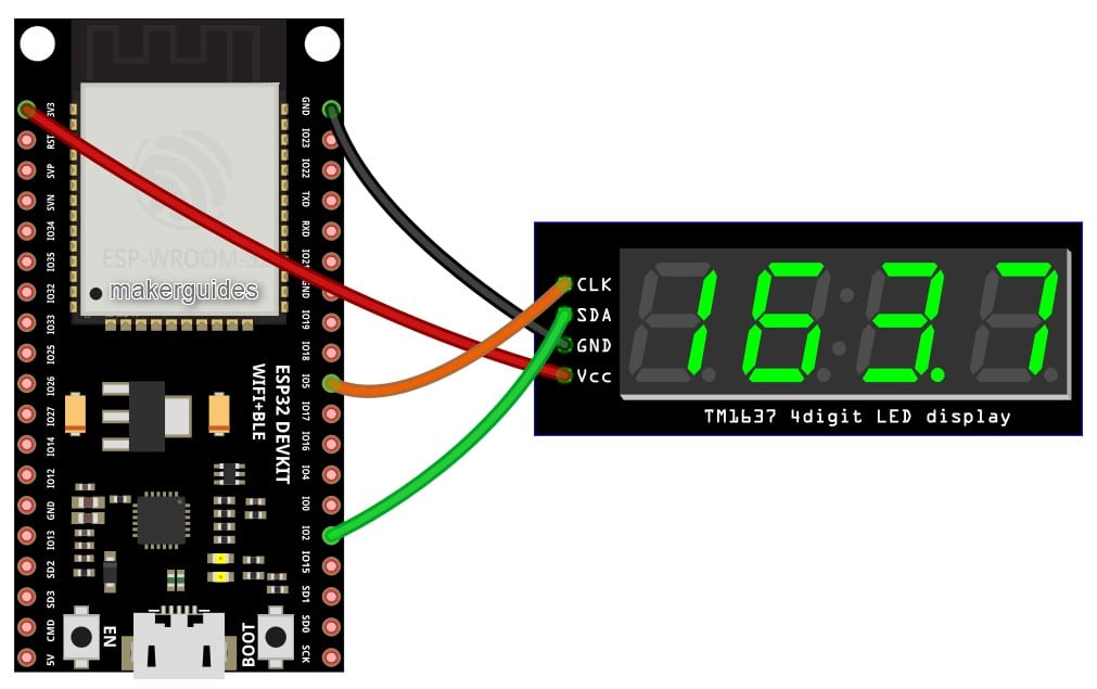
I use GPIO5 and GPIO12 for CLK and Data, but you can use any pin.
Make sure to connect the ground pins first before connecting other pins. Also, connect power only after completing all the connections.
ESP32 And TM1637 Code Example
You can use the code below to test the ESP32 module and the ITM1637 LED driver project.
Please follow the guide to install the ESP32 core on the Arduino IDE.
#include "TM1637Display.h"

// Module connection pins (Digital Pins)
#define CLK 15
#define DIO 2

// The amount of time (in milliseconds) between tests
#define TEST_DELAY   2000

const uint8_t SEG_DONE[] = {
  SEG_B | SEG_C | SEG_D | SEG_E | SEG_G,           // d
  SEG_A | SEG_B | SEG_C | SEG_D | SEG_E | SEG_F,   // O
  SEG_C | SEG_E | SEG_G,                           // n
  SEG_A | SEG_D | SEG_E | SEG_F | SEG_G            // E
};

TM1637Display display(CLK, DIO);

void setup()
{
}

void loop()
{
  int k;
  uint8_t data[] = { 0xff, 0xff, 0xff, 0xff };
  uint8_t blank[] = { 0x00, 0x00, 0x00, 0x00 };
  display.setBrightness(0x0f);

  // All segments on
  display.setSegments(data);
  delay(TEST_DELAY);

  // Selectively set different digits
  data[0] = display.encodeDigit(0);
  data[1] = display.encodeDigit(1);
  data[2] = display.encodeDigit(2);
  data[3] = display.encodeDigit(3);
  display.setSegments(data);
  delay(TEST_DELAY);

  display.clear();
  display.setSegments(data + 2, 2, 2);
  delay(TEST_DELAY);

  display.clear();
  display.setSegments(data + 2, 2, 1);
  delay(TEST_DELAY);

  display.clear();
  display.setSegments(data + 1, 3, 1);
  delay(TEST_DELAY);

  // Show decimal numbers with/without leading zeros
  display.showNumberDec(0, false); // Expect: ___0
  delay(TEST_DELAY);
  display.showNumberDec(0, true);  // Expect: 0000
  delay(TEST_DELAY);
  display.showNumberDec(1, false); // Expect: ___1
  delay(TEST_DELAY);
  display.showNumberDec(1, true);  // Expect: 0001
  delay(TEST_DELAY);
  display.showNumberDec(301, false); // Expect: _301
  delay(TEST_DELAY);
  display.showNumberDec(301, true); // Expect: 0301
  delay(TEST_DELAY);
  display.clear();
  display.showNumberDec(14, false, 2, 1); // Expect: _14_
  delay(TEST_DELAY);
  display.clear();
  display.showNumberDec(4, true, 2, 2);  // Expect: __04
  delay(TEST_DELAY);
  display.showNumberDec(-1, false);  // Expect: __-1
  delay(TEST_DELAY);
  display.showNumberDec(-12);        // Expect: _-12
  delay(TEST_DELAY);
  display.showNumberDec(-999);       // Expect: -999
  delay(TEST_DELAY);
  display.clear();
  display.showNumberDec(-5, false, 3, 0); // Expect: _-5_
  delay(TEST_DELAY);
  display.showNumberHexEx(0xf1af);        // Expect: f1Af
  delay(TEST_DELAY);
  display.showNumberHexEx(0x2c);          // Expect: __2C
  delay(TEST_DELAY);
  display.showNumberHexEx(0xd1, 0, true); // Expect: 00d1
  delay(TEST_DELAY);
  display.clear();
  display.showNumberHexEx(0xd1, 0, true, 2); // Expect: d1__
  delay(TEST_DELAY);

  // Run through all the dots
  for (k = 0; k <= 4; k++) {
    display.showNumberDecEx(0, (0x80 >> k), true);
    delay(TEST_DELAY);
  }

  // Brightness Test
  for (k = 0; k < 4; k++)
    data[k] = 0xff;
  for (k = 0; k < 7; k++) {
    display.setBrightness(k);
    display.setSegments(data);
    delay(TEST_DELAY);
  }

  // On/Off test
  for (k = 0; k < 4; k++) {
    display.setBrightness(7, false);  // Turn off
    display.setSegments(data);
    delay(TEST_DELAY);
    display.setBrightness(7, true); // Turn on
    display.setSegments(data);
    delay(TEST_DELAY);
  }

  // Done!
  display.setSegments(SEG_DONE);

  while (1);
}
Code walkthrough
The code begins by including the necessary libraries and defining the connection pins for the TM1637 display module.
#include "TM1637Display.h"
After that, the code defines a constant for the delay time between each test (in milliseconds). You can change the code to your liking.
#define TEST_DELAY 2000
Also, define an array of values for displaying the word “DONE” on the LED display.
const uint8_t SEG_DONE[] = {
  SEG_B | SEG_C | SEG_D | SEG_E | SEG_G,           // d
  SEG_A | SEG_B | SEG_C | SEG_D | SEG_E | SEG_F,   // O
  SEG_C | SEG_E | SEG_G,                           // n
  SEG_A | SEG_D | SEG_E | SEG_F | SEG_G            // E
};
The setup() function is empty, meaning it will not run any initialization code.
The loop() function is where all the tests are performed.
First, it sets the brightness level of the display to the maximum.
display.setBrightness(0x0f);
Then, it briefly displays all segments of the four digits before selectively displaying each number (0, 1, 2, and 3) one at a time for the same duration.
The code then clears the display and displays the digits 2 and 3 together, 1 and 2 together, and finally, 1, 2, and 3 together.
The next section of the code shows how to display decimal and hexadecimal numbers on the LED display.
It shows decimal numbers with and without leading zeros and negative numbers. It also displays hexadecimal numbers and runs through all the dots on display.
  // Brightness Test
  for (k = 0; k < 4; k++)
    data[k] = 0xff;
  for (k = 0; k < 7; k++) {
    display.setBrightness(k);
    display.setSegments(data);
    delay(TEST_DELAY);
  }
The above code tests the display’s brightness levels, from 0 (off) to 7 (maximum brightness).
  // On/Off test
  for (k = 0; k < 4; k++) {
    display.setBrightness(7, false);  // Turn off
    display.setSegments(data);
    delay(TEST_DELAY);
    display.setBrightness(7, true); // Turn on
    display.setSegments(data);
    delay(TEST_DELAY);
  }
This code provides a helpful example for anyone looking to interface a TM1637 display with an ESP32 board. I hope this explanation helps!
Let me know if you have any other questions.
FAQs About The ESP32 And The TM1637 LED Driver
I have included a list of the most frequently asked questions about projects built using the ESP32 and the 4-digit LED driver TM1637.
If you have more questions, please post them in the comments section. I will be glad to answer them.
What is TM1637?
TM1637 is a LED driver chip that drives 7-segment LED displays. It is commonly used in clocks, timers, and other devices that require a simple numerical display.
It is very easy to connect the module to ESP32 and Arduino alike.
How many digits can a TM1637 display?
A TM1637 chip can drive up to four 7-segment digits. TM1637 is a low-cost, simple LED driver. Other versions can do more stuff (TM1638, for example).
What kind of displays can be used with TM1637?
TM1637 is typically used with 7-segment LED displays but can also be used with 14-segment LED displays.
How do you connect TM1637 to a microcontroller?
TM1637 uses a two-wire interface (CLK and DIO) to communicate with a microcontroller. The CLK pin is used to synchronize data transfer, while the DIO pin is used to send data.
In this article, I have taught how to connect an LED module with TM1637 to an ESP32.
How do you control the display with TM1637?
To control the display with TM1637, you send commands to the chip over the two-wire interface. The chip can turn individual segments on and off, set the display’s brightness, and control the colon (:) separator.
For example, the colon operator can be used when you are using the LED segments to show a clock or a stopwatch.
What programming languages are commonly used with TM1637?
TM1637 can be programmed using a variety of languages, including C, C++, Python, and Arduino. In this article, we have used an Arduino-compatible sketch.
Can TM1637 display letters and symbols?
The LED Driver IC TM1637 can only display numbers and a colon (:) separator. If you need to display letters and symbols, you will need a different type of display. (TM1638, for example).
What is the maximum brightness of TM1637?
TM1637 can be set to 8 different brightness levels, with level 0 being the dimmest and level 7 being the brightest. Brightness settings help.
During the day, you can make the display more visible, and during night time (or in the dark), you can save power and make the display more plausible.
Conclusion
In this article, I have covered all the information you need to know to use the ESP32 and TM1637 LED Driver confidently.
I have provided the connecting guide and a working ESP32 TM1637 LED Driver example code to get started faster.
The FAQs and the basics section of the article have covered all the essential information needed. If you still have questions, I am happy to help you. Please share them in the comments.
Would you like to suggest any improvement to the current article? What would you like to read about next? Please share your thoughts in the comment section.
Keep Learning!

I am Puneeth. I love tinkering with open-source projects, Arduino, ESP32, Pi and more. I have worked with many different Arduino boards and currently I am exploring, Arduino powered LoRa, Power line communication and IoT.