Solenoids are electromagnetic devices that are commonly used in various applications such as locking mechanisms, valves, and actuators. In this blog post, you will learn about the different types of solenoids, how to control a solenoid with an Arduino using a Relay module or a power transistor (TIP120).
Let’s start with the required parts.
Required Parts
Makerguides.com is a participant in the Amazon Services LLC Associates Program, an affiliate advertising program designed to provide a means for sites to earn advertising fees by advertising and linking to products on Amazon.com. As an Amazon Associate we earn from qualifying purchases.
Below you will find the parts required for this project. I assume you already have a solenoid you want to control but you can find many different types of solenoids here.
We are going to use a TIP120 Transistor for some of the circuits in this article. I provided a link to a transistor kit with various transistors, which is handy to have – in case you need a different type. But you can find a pack of only TIP120 here.

Arduino Uno

Dupont Wire Set

Breadboard

USB Cable for Arduino UNO

Resistor & LED kit
Relay Module
Transistor Kit
Now you have all the required parts, let’s get started.
How Does a Solenoid Work?
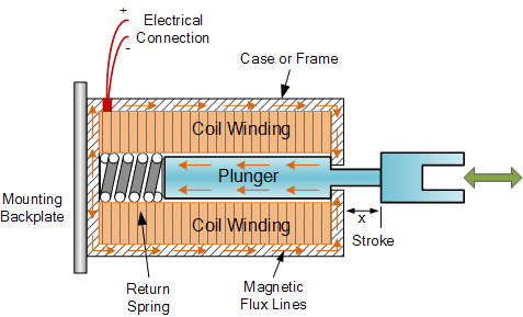
A solenoid is an electromechanical device that converts electrical energy into linear motion. It consists of a coil of wire wound around a cylindrical core, usually made of iron or steel. When an electric current flows through the coil, it creates a magnetic field that pulls in a movable plunger. Once the current stops, a spring pushes the plunger back out. See the picture below.
The basic principle behind the operation of a solenoid is Ampere’s law, which states that a magnetic field is produced around a current-carrying conductor. In the case of a solenoid, the coil acts as the conductor, and the current flowing through it generates a magnetic field.
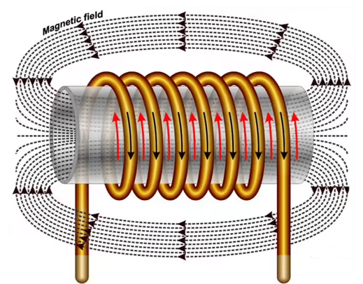
When the current flows through the coil, the magnetic field lines concentrate inside the coil, creating a strong magnetic force. This force attracts the plunger, causing it to move towards the center of the coil. When the current is turned off, the magnetic field collapses, and the plunger returns to its original position due to a spring or other mechanical means.
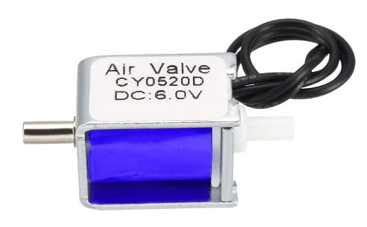
Solenoids are commonly used in various applications, such as door locks, valves, actuators, and relays. They provide a reliable and efficient way to control mechanical movements using electrical signals. Below a picture of a small solenoid valve.
In the next sections, we will explore the different types of solenoids and discuss the circuits and code required to control them using an Arduino.
Types of Solenoids
Solenoids come in various types, each designed for specific applications. Understanding the different types will help you choose the right solenoid for your project. Here are some common features of solenoids to take into account:
Motion
- Linear solenoids: These solenoids produce linear motion, where the plunger moves in a straight line.
- Rotary solenoids: These solenoids produce rotary motion, where the plunger rotates around an axis.
- Push-pull solenoids: These solenoids are Linear Solenoids that provide both pushing and pulling forces.
- Proportional solenoids: These solenoids are designed to provide variable force or motion control.
Latching vs Non-latching
- Latching solenoids: These solenoids have two stable positions and require a pulse of current to switch between them. Once the pulse is applied, they remain in the new position without continuous power.
- Non-latching solenoids: These solenoids return to their original position when the power is removed.
Intermittent vs Continuous
- Intermittent solenoids: These solenoids can only be powered for a short time. A few seconds, typically before they get very hot and potentially burn out!
- Continuous solenoids: These solenoids can be powered continuously without getting too hot.
AC vs DC
- AC solenoids: These solenoids are designed to operate with alternating current (AC) power supply.
- DC solenoids: These solenoids are designed to operate with direct current (DC) power supply.
It’s important to note that solenoids can have combinations of these characteristics. For example, a solenoid can be a linear, non-latching, intermittent solenoid that operates with DC power. Also there are many more types for specific applications than the few coarse categories described above.
In the next section we highlight what to watch out for when switching inductive loads such as solenoids (or motors, or relays).
Switching of Inductive Loads
When we switch inductive loads like solenoids, we can encounter very high voltage spikes due to the inductance of a solenoids. These voltage spikes occur because of the sudden change in current flow when we open or close the switch controlling the solenoid.
Inductors resist changes in current flow. So when we open the switch, the inductor tries to maintain the current by generating a voltage spike in the opposite direction. Similarly, when we close the switch, the inductor resists the sudden increase in current, resulting in another voltage spike.
These voltage spikes can be problematic as they potentially damage sensitive electronic components such as your Arduino or cause interference in nearby circuits. To avoid this, we can use flyback diodes, also known as freewheeling diodes or snubber diodes.
Circuit with Flyback Diode
A Flyback diode is connected in parallel with the solenoid (see picture below), with the cathode connected to the positive terminal of the solenoid and the anode connected to the negative terminal. When we open the switch, the current flowing through the solenoid tries to continue flowing, but instead of generating a voltage spike, it circulates through the flyback diode.
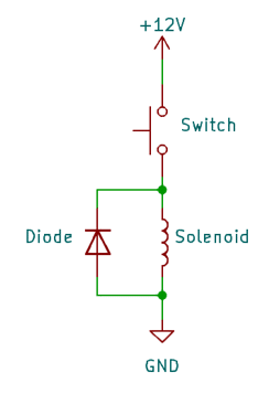
We essentially create a short-cut for the voltage spike that dissipated its energy by heating up the diode. This effectively protects the rest of the circuit from potential damage.
When selecting a flyback diode, it is therefore important to choose one with a suitable current and voltage rating to handle the voltage spike. Additionally, the diode should have a fast recovery time to effectively suppress the voltage spikes.
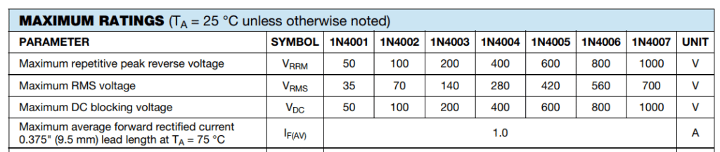
Diode ratings
What specific diode to choose will depend on the specifics of the inductive load (Solenoid). However, generally a 1N4002 or better will do fine in most cases. It can deal with voltage spikes of up to 100V. See the ratings of the different 1N400X diodes below.
Note that you only need flyback diodes when switching solenoids on DC power. For AC powered solenoids you typically don’t use flyback diodes.
In the next sections, we will learn how to control solenoids using an Arduino, whether through a relay module or a TIP120 transistor.
Circuit to control a Solenoid using a Relay
Let’s start with the simplest possible circuit first.
Switching an AC Solenoid
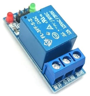
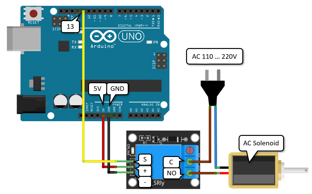
We switch an AC solenoid running on 110V or 220V AC using a relay module. See the circuit below. It consists of an Arduino, a Relay Module, an AC Solenoid which is connected to mains power!
While the circuit is simple, it is also dangerous, since we are switching high voltages. Be careful!
First connect the plus and minus pins of the Relay Module to the 5V and GND pins of the Arduino. We will control the relay from pin 13 of the Arduino. So connect pin 13 to the signal pin (S) of the relay module as well.
Now, you can and should test the function of the circuit. Upload the following code to your Arduino.
const uint8_t solenoidPin = LED_BUILTIN;

void setup() {
  pinMode(solenoidPin, OUTPUT);
}

void loop() {
  digitalWrite(solenoidPin, HIGH);
  delay(1000);
  digitalWrite(solenoidPin, LOW);
  delay(1000);
}
It switches the relay on for a second and then off for a second. You should see the built in LED switch on and off and you also should hear a clicking sound from the relay, when it switches.
If that works, you can connect the solenoid to the relay and the mains power. Now be very careful with this. Don’t touch any bare wires! Solenoids have no polarity, so it doesn’t matter in which order to connect the solenoid pins.
However, when connecting the relay to mains power you should connect the brown (or red) wire to the C (common) pin of the relay module and then from the NO (normally open) pin to the solenoid. The brown (or red) wire is typically the life wire but the color codes depend on the country. Make sure that your relay is rated to switch 110V/220V and the current needed by the solenoid!
Switching a DC Solenoid
Switching a DC Solenoid is essentially identical to switching an AC Solenoid. There is only one difference. We need to add the flyback diode – and of course, need a DC power supply. See the circuit below.
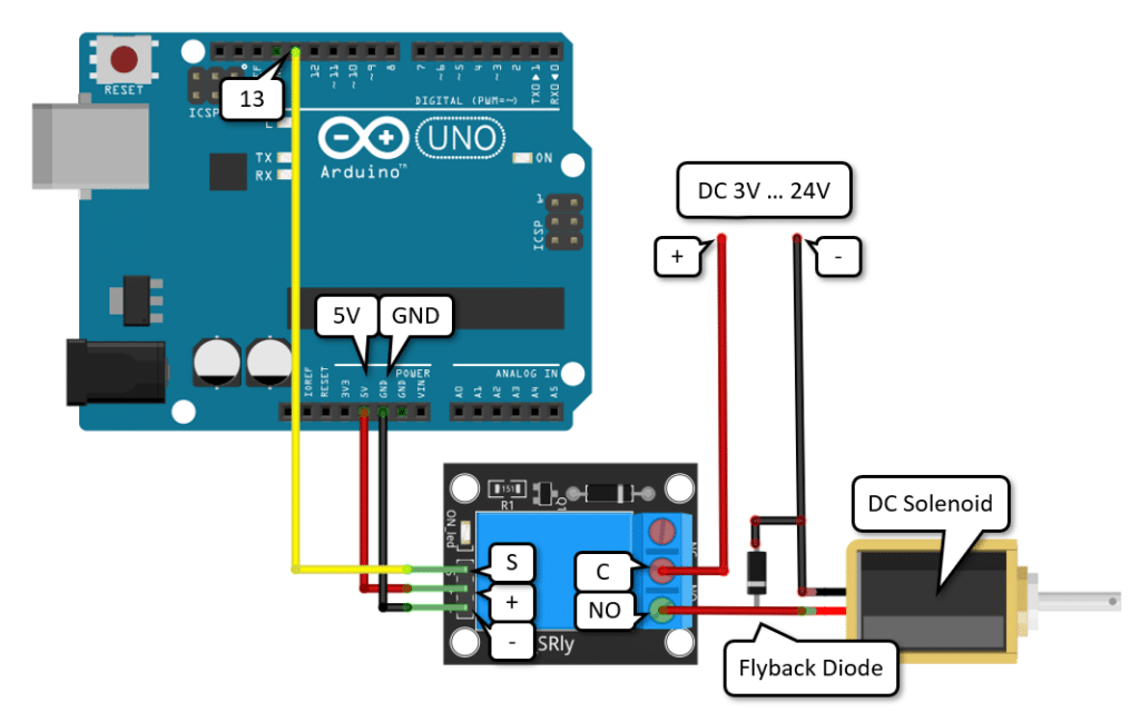
Connect the Relay Module and the power as before. Then add the Flyback Diode between the positive and negative wire that provides power to the Solenoid. Make sure that the Diode is in the correct orientation. The side marked with the ring must be connected to the positive wire – otherwise you are creating a shortcut!
Most DC Solenoids will need supply voltages between 3V to 24V. You need to check what the required voltage for your Solenoid is. In addition, make sure to check the current requirements. Even very small Solenoids can easily pull more than 1A of current and your power supply must be able to deliver that current. That means, typically you cannot power the solenoid from the 5V pin of the Arduino but must use a separate power supply.
Finally, watch out for solenoids that can be powered only for a few seconds (intermittent), which are most of them! If you use one of those ones, and keep it switch on for too long it will get very hot and might burn out! Check the datasheet of the Solenoid and check its temperature when switching it/
Circuit to control a Solenoid using a Transistor
The two circuits above are simple and great if you don’t switch the solenoid very often (a few times in a day). However, if you need to switch a solenoid frequently, you should use a transistor, since a relay will fail after a while due to the mechanical stress.
There are two types of transistors typically used for these kinds of tasks. Bipolar junction transistors (BJT) or Metal–Oxide–Semiconductor Field-Effect Transistors (MOSFET). If you want to use a MOSFET, have a look at our tutorial on How to Control a Fan using Arduino.
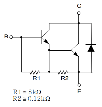
Here we will use a BJT. Specifically we will use the common TIP120, which is actually a Darlington Transistor compose of two BJTs. It can switch up to 60V and a continuous current of 5A (peak 8A), which is sufficient for most Solenoids – but check your Solenoid to be sure. For more details about the TIP120 transistor see the datasheet below:
Base Transistor Circuit
The following schematics shows how to use the TIP120 to control a Solenoid from a GPIO pin. Note the Flyback Diode in parallel to the Solenoid, and the Resistor that connects the GPIO pin with the base of the Transistor.
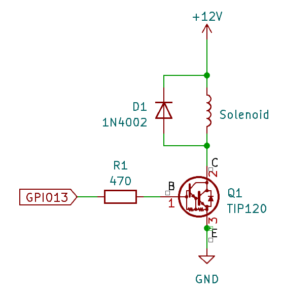
The TIP120 has an internal Flyback diode (see schematics below). But to be on the safe side we add our own one. Also, this way you can swap out the transistor without having to change the circuit.
Base Resistor Value Calculation
When designing such a circuit the most important question to answer is which base resistor to use. If the resistor is too small the current draw on the GPIO pin could be so high that your Arduino will be damaged. If the base resistor is too large the transistor will not switch completely on, and the solenoid will not act.
We can calculate the value for the base resistor as follows. We want the current draw on the GPIO pin to be smaller than 20mA (max current is 40mA for an Arduino Uno). On the other hand, we want the collector current to be larger than the current required for the Solenoid, let’s say that is 2A.
The base current Ib (the current at the GPIO pin) can be calculated as
Ib = (5V – 0.7V) / Rb = 4.3V / Rb
We want an Ib <= 20mA and therefore get a base resistor Rb of at least
Rb = 4.3V / Ib = 4.3V / 20mA = 215Ω
The TIP120 has a current gain (hfe) of around 1000. Which means, with a base current Ib of 20mA x 1000 we would get a collector current Ic of 20A. We don’t need that much, since the TIP120 is rated for 8A max peak anyway.
If we pick a 470Ω resistor instead, the base current Ib will be Ib = (5V – 0.7V) / 470Ω = 9.1mA and the collector current will be 9mA x 1000 = 9A, which is a much better fit. So any base resistor between 470Ω up to 1 or 2KΩ, will work fine.
Note however, that you will need extra cooling if you want to run the TIP120 anywhere near its peak current. But switching a 12V Solenoid at 1A shouldn’t be a problem.
Complete Circuit
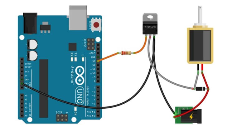
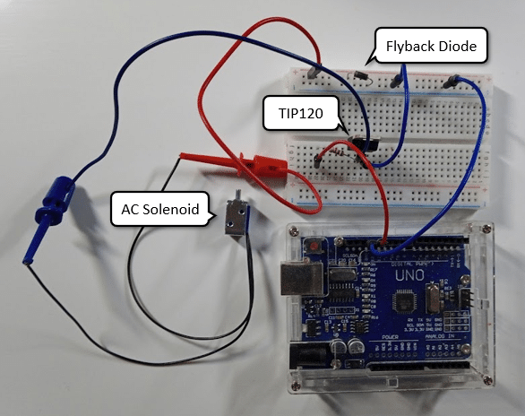
The following picture shows the complete circuit to control a Solenoid with a TIP120 transistor using an Arduino UNO.
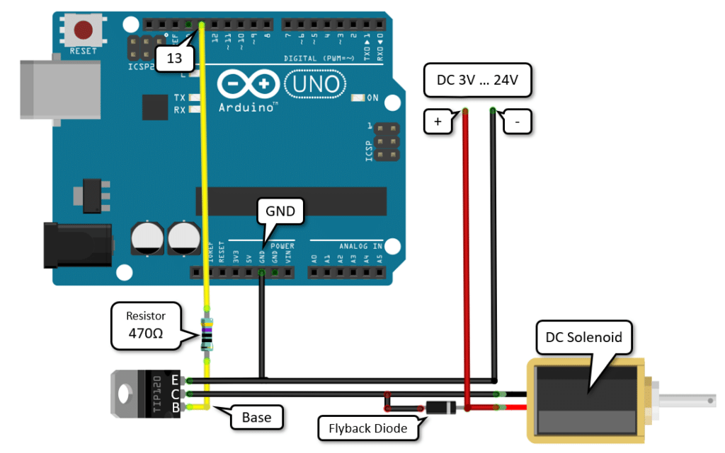
For the wiring, start by connecting pin 13 of the Arduino via the 470Ω resistor to the base pin (B) of the TIP120 transistor (yellow wire).
Then connect GND of the Arduino to the Emitter pin (E) of the TIP120 and to ground (-) of the external power supply (black wire).
Next connect the Collector pin (C) of the TIP120 to one pin of the Solenoid and connect the positive pole of the power supply (+) to the other pin (red wire).
Finally add the Flyback diode by connecting the side with the ring to the positive wire and the other side to the other pin of the Solenoid.
Here a picture of the completed circuit on a breadboard, however, without the external power supply that drives the Solenoid:
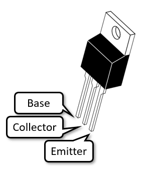
When connecting the TIP120 make sure that you connect the pins correctly. The picture below show the pinout of the TIP120.
And there you have it! Two different circuits to control a Solenoid using an Arduino. In the next section, we will have a look at the code needed.
Example Code to Control a Solenoid
The following example code to control the Solenoid is extremely simple. It is essentially just the good ole’ Blink sketch, which we used abve. Have a look.
const uint8_t solenoidPin = LED_BUILTIN;

void setup() {
  pinMode(solenoidPin, OUTPUT);
}

void loop() {
  digitalWrite(solenoidPin, HIGH);
  delay(1000);
  digitalWrite(solenoidPin, LOW);
  delay(1000);
}
We are going to use pin 13, which is also connected to the built-in LED (LED_BUILTIN). This has the advantage that you can see when the transistor switches on or off. But you can use any other digital IO pin as well and add your own LED if you want to.
Constants and Variables
We start by defining the constant solenoidPin which specifies the pin to which the solenoid is connected.
const uint8_t solenoidPin = LED_BUILTIN;
Setup function
In the setup() function, we set the mode of solenoidPin to OUTPUT since we will be writing to it.
void setup() {
  pinMode(solenoidPin, OUTPUT);
}
Loop function
The loop() function is where the main logic of the code resides. In this function, we first set the solenoid pin to HIGH to switch the solenoid on. We then introduce a delay of 1000ms (1 second) using the delay() function. This keeps the solenoid on for 1 second. After that, we set the solenoid pin to LOW to switch the solenoid off and introduce another delay of 1 second. This creates a cycle where the solenoid is switched on and off every second.
void loop() {
  digitalWrite(solenoidPin, HIGH);
  delay(1000);
  digitalWrite(solenoidPin, LOW);
  delay(1000);
}
This loop runs continuously, ensuring that the solenoid is repeatedly switched on and off at regular intervals.
Example Code to Control a Solenoid from Sensor
For most practical applications you will have to modify this sketch. For instance, to switch on the Solenoid for 5 seconds, if a sensor value drops below a certain threshold you would write code similar to the following.
const uint8_t solenoidPin = LED_BUILTIN;
const uint8_t sensorPin = A0;
const int threshold = 500;

void setup() {
  pinMode(solenoidPin, OUTPUT);
  pinMode(sensorPin, INPUT);
}

void loop() {
  int sensorValue = analogRead(sensorPin);
  if (sensorValue < threshold) {
    digitalWrite(solenoidPin, HIGH);
    delay(5000);
    digitalWrite(solenoidPin, LOW);
  }
  delay(100);
}
Use this code as a template for your own application and have a look at our tutorials that cover all kinds of sensors. For instance, you could build a door lock using an RFID reader, a pet feeding station using a motion sensor, or a plant watering system using a moisture sensor.
Conclusion
In conclusion, solenoids are versatile devices that can be controlled using an Arduino to perform various tasks. We have learned about the different types of solenoids and how they work. By using either a relay module or a TIP120 transistor, we can easily control the solenoid’s operation.
Solenoids are commonly used in applications such as door locks, valves, and robotic mechanisms. They provide a reliable and efficient way to convert electrical energy into mechanical motion. With the help of an Arduino, we can easily integrate solenoids into our projects and automate various tasks.
When it comes to controlling a solenoid with an Arduino, we have discussed two common methods. The first method involves using a relay module, which provides isolation between the Arduino and the solenoid, ensuring the safety of the microcontroller. The second method involves using a TIP120 transistor, which allows us to control the solenoid using a smaller current from the Arduino.
Both methods have their advantages and disadvantages. The relay module provides better isolation and can handle higher currents, making it suitable for heavy-duty applications. On the other hand, the TIP120 transistor is more compact and cost-effective, making it suitable for smaller projects with lower power requirements.
The relay module acts as a switch, allowing us to control the solenoid’s operation by toggling the relay on and off. While the transistor acts as a current amplifier, allowing us to control the solenoid’s operation by varying the current flowing through it.
In both cases, we have provided example circuits and code snippets to help you get started with controlling a solenoid using an Arduino. Feel free to experiment with different solenoid types and configurations to suit your specific project requirements.
Frequently Asked Questions
Q: What is a solenoid?
A: A solenoid is an electromechanical device that converts electrical energy into (linear) motion. It consists of a coil of wire wrapped around a ferromagnetic core. When current flows through the coil, a magnetic field is generated, causing the core to move.
Q: What are the different types of solenoids?
A: There are various types of solenoids, each designed for specific applications. Some common types include:
- Pull-Type Solenoids: These solenoids are designed to pull or retract a plunger when energized. They are commonly used in applications such as door locks and pneumatic valves.
- Push-Type Solenoids: These solenoids are designed to push or extend a plunger when energized. They are often used in applications such as automotive starter motors and fuel injectors.
- Tubular Solenoids: These solenoids have a tubular shape and are used in applications that require a linear motion, such as vending machines and medical devices.
- Rotary Solenoids: These solenoids convert electrical energy into rotary motion. They are commonly used in applications such as door locks and automated machinery.
Q: How can I control a solenoid with an Arduino?
A: There are two common methods to control a solenoid with an Arduino: using a relay module or a TIP120 transistor.
- Relay Module: A relay module acts as a switch that can handle high currents. It allows the Arduino to control the solenoid by providing a separate power source for the solenoid. The Arduino controls the relay module, which in turn controls the solenoid.
- TIP120 Transistor: A TIP120 transistor can also be used to control a solenoid. The transistor acts as a switch that allows the Arduino to control the solenoid’s current flow. The Arduino sends a signal to the transistor, which then controls the solenoid.
Q: Can I directly connect a solenoid to an Arduino?
A: It is generally not recommended to directly connect a solenoid to an Arduino. Solenoids often require higher currents than what an Arduino can provide. Directly connecting a solenoid to an Arduino can damage the board or cause it to malfunction. It is safer to use a relay module or a transistor to control the solenoid.
Q: What is the difference between intermittent and continuous Solenoids?
Intermittent Solenoids can be switched on only intermittently (typically a few seconds) before the get hot and finally burn out. Most Solenoids are of this type. So make sure to let them cool down and not switch them to frequently.
Continuous Solenoids on the other hand can be continuously powered and don’t get overly hot.
Q: Are there any safety precautions I should take when working with solenoids?
A: Yes, there are a few safety precautions to keep in mind when working with solenoids:
- Power Supply: Ensure that the power supply for the solenoid is appropriate for its requirements. Using an incorrect power supply can damage the solenoid or cause it to malfunction.
- Current Limiting: Use appropriate current-limiting resistors or components to protect the Arduino from excessive current flow.
- Isolation: If the solenoid is controlling a high-voltage or high-power circuit, consider using isolation techniques to protect the Arduino and other sensitive components.
- Heat Dissipation: Solenoids can generate heat during operation. Ensure that the solenoid is properly cooled to prevent overheating.
Always check the specifications of the solenoid you are using, and be very careful when working with mains voltages!
But have fun ; )

I am Puneeth. I love tinkering with open-source projects, Arduino, ESP32, Pi and more. I have worked with many different Arduino boards and currently I am exploring, Arduino powered LoRa, Power line communication and IoT.
William
Friday 12th of April 2024
I am new to working with the arduino. I would like to control a 120V solenoid to ring a bell every 3 sec for one minute and then stop, a couple times a week. The instruction above sound like they will work, but for 120v it sounds like I should use the relay not the transistor. I was hoping to control the weekly timing with a simple 120v digital timer. am i going in the right direction? Thanks
Stefan Maetschke
Friday 12th of April 2024
Hi, Yes, if you just want to ring an existing 120V bell for a few seconds on an not too complex schedule, the a digital timer plug is probably the easiest way to go, e.g. https://amzn.to/3JidHqi
If the schedule is complex, a digital timer plug might not be able to do it. If you want to use an Arduino/ESP32 in this case, then a relay is indeed recommended. Probably a solid state relay.
sajad
Friday 29th of December 2023
hello i made solenoid with arduino it turns on but it dosnt turn off what i have to do abut that? [email protected]
Athena
Saturday 9th of March 2024
@Stefan Maetschke, the solenoid does turn on when I disconnect the base resistor. I will recheck my orientation of the transitor.
Athena
Saturday 9th of March 2024
@Stefan Maetschke, I have this same issue. I will start by removing the resistor and see if that helps.
Stefan Maetschke
Friday 29th of December 2023
Without seeing the actual circuit and code it is hard to tell but first I would check that the transistor (TIP120) is correctly connected. Does the solenoid switch off when you disconnect the base resistor?
hassina
Thursday 10th of August 2023
hello , please if you can to help me . i have solenoid that turn on with 5V and turn off with -5V HOW can i controlle this with arduino
Stefan
Friday 11th of August 2023
You could use an H-Bridge or a DPDT Relay instead of the single transistor to switch the polarity. https://en.wikipedia.org/wiki/H-bridge https://electronics.stackexchange.com/questions/58482/circuit-to-reverse-polarity
Peter
Saturday 10th of December 2022
Hello I like what you’ve done in this tutorial, it’s clear and concise. I want to built an array of five normally open solenoids each activated at a specified temperature thru a thermoprobe Can you steer me how to go about doing that Peter